Predictive Maintenance in real world
Introduction
In this article I am going to explain the concept of predictive maintenance, and why it should be used in any actual application which suffers from time deterioration.
The example application we will focus on is the status report of an electric drive, used in modern applications such as autonomous vehicles or industrial robotics.
The aim of the predictive maintenance is to predict ahead of time eventual faults of the system based on the current status.
We now briefly introduce electrical drives and motor control and then use them to understand how to predict their status.
Electrical Drives
We will now briefly detail the physics principle of actuation of a DC motor:
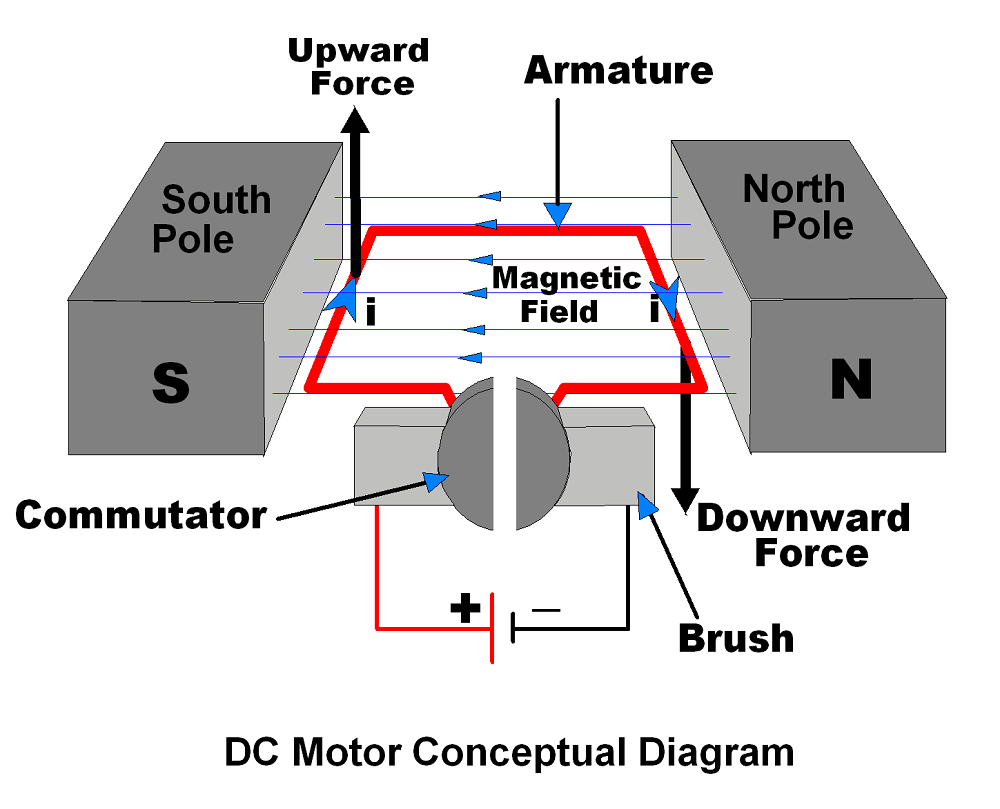
The figure above is composed of 3 most important elements:
- Two magnets with different polarity, one North and one South.
- One armature where current can flow
- A generator capable to generate a differential such that current can flow from its positive part to its negative through the armature
What happens when we turn on the generator?
When the current starts to flow in the armature, this last one will start to rotate. The rotation is given by the Lorentz force. We can see the current flow through a conductor as an ordered set of single particles that moves from a positive side to a negative one. If we embed those flows of particles into a magnetic field (as happens to the armature between the two magnets), the Lorentz force will act orthogonally with respect to the flow of the particles, and that’s what generates the rotation.
The modern electric drives are composed of an electric motor (such as DC brushed motors, presented above) and power electronics, such as SiC (Silicon Carbide) or GaN (Gallium Nitride) used to give command to the motor.
To conclude, a possible reference design could be the following:

Motor Control
The previous block diagram represents an open loop system, where the command generated propagates from source to motor. In this case we “hope” that the motor will behave correctly, because no control has been implemented.
What we need then is feedbacking some motor information to our command generator. The feedback helps us understand i.e. the position of the motor to generate an appropriate input for the power electronics from the command generator.
We now add two block to create a working diagram, or rather a motor controller and a status reporter:
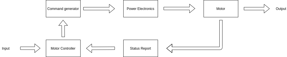
The status report is meant as any component of the system which can read a particular information on currents or position of the rotor (referred before as armature). An example are the AB-Encoders, which can feedback the position of the rotor.
The Motor Controller is a structure which can interpret the status reported and apply a correction law which makes the motor move according to the given input. An example of this is the PID controller.
The command generator is usually a Pulse Width Modulator.
Before moving onto the next chapter let me state that the blocks Status Report, Motor Controller and Command Generator are generally grouped under a single block called Vector Motor Control. The two most famous techniques of Vector Motor Control are the Direct Torque Control (DTC) and the Field Oriented Control (FOC).
Motor Health Status Reporting
Now that we know how to control an electric drive, we also want to try to understand how to check whether the motor has some faults or not.
There are many ways to do that, but we will focus on using Neural Networks.
Neural Networks are complex systems which are able to understand complex patterns of specific problems due to the non-linearity of their formulation. If the reader wants to know more about them, we have already explained them in another detailed article: AI edge platform on zynq fpga
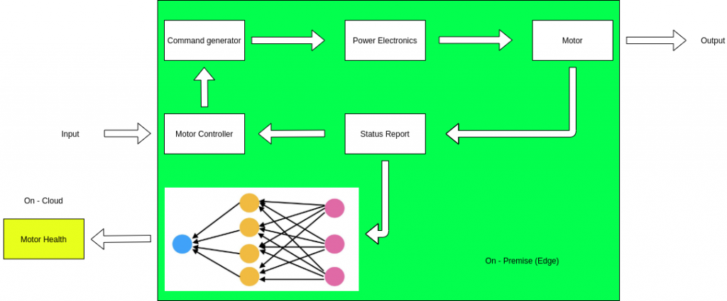
Let’s recall the previous scheme:
How do we understand from this closed loop system, where to find out some faults?
A possible answer is in the arrow from Status Report to Motor Controller. In this case we will use a neural network which will classify the possible health of the motor. A simple classification could be healthy or unhealthy.
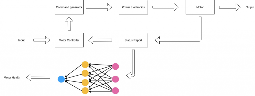
The above block diagram represent a modern Predictive Maintenance system, which can be used by any electric drives and can report in real-time (depending on the architecture chosen, i.e. FPGA performs computations in hard real time) whether the motor has some faults or not.
Cloud Computing Vs Edge Computing
I want now to briefly introduce the difference between edge and cloud computing. Edge computing happens when information are processed locally to their generation, or rather, they do not need to be transferred using the Internet. On the other hand Cloud Computing happens when information are processed or stored in a different location from their generation.
Predictive Maintenance is a perfect use-case for both of them, because the motor controller and health classification can be done locally (on the edge) whereas the health report could be stored in cloud to avoid memory or database usage at the edge (i.e. an industry which needs to store locally some customer or partner data it needs the highest memory amount possible). The scheme then enlights the difference between edge and cloud computing in Predictive Maintenance:
Conclusion
In this article we have shown a possible usage of predictive maintenance for modern electric drives based on Neural Networks.
The reference architecture used in the project are the Zynq UltraScale+ MPSoCs, such as ZU3EG or ZU7EV.
Hope the reader enjoyed the article.
Enjoy your acceleration,
Guglielmo Zanni
Principal Scientist @MakarenaLabs – Research Fellow @Altair Laboratory