Creating a DPU-Compatible Platform for PYNQ
Introduction
In this tutorial, we will show how to create a custom hardware design with Xilinx’s DPU IP provided in the Vitis AI toolchain. Specifically, you can use this approach with any custom design which is Vivado compatible, and you can extend it to infer AI models.
What is the DPU IP
The Xilinx® Deep Learning Processor Unit (DPU) is a programmable engine dedicated for convolutional neural network. The unit contains register configure module, data controller module, and convolution computing module. There is a specialized instruction set for DPU, which enables DPU to work efficiently for many convolutional neural networks.
You can use the DPU IP as a block in the programmable logic (PL) of the selected Zynq®-7000 SoC and Zynq UltraScale™+ MPSoC devices with direct connections to the processing system (PS). To use DPU, you should prepare the instructions and input image data in the specific memory address that DPU can access. The DPU operation also requires the application processing unit (APU) to service interrupts to coordinate data transfer.
Step 0: Basic Design without other components
As a first step, we need to know what are the connections of a plain design with only the DPU in it, to have the clearest idea possible of what are the connections needed:
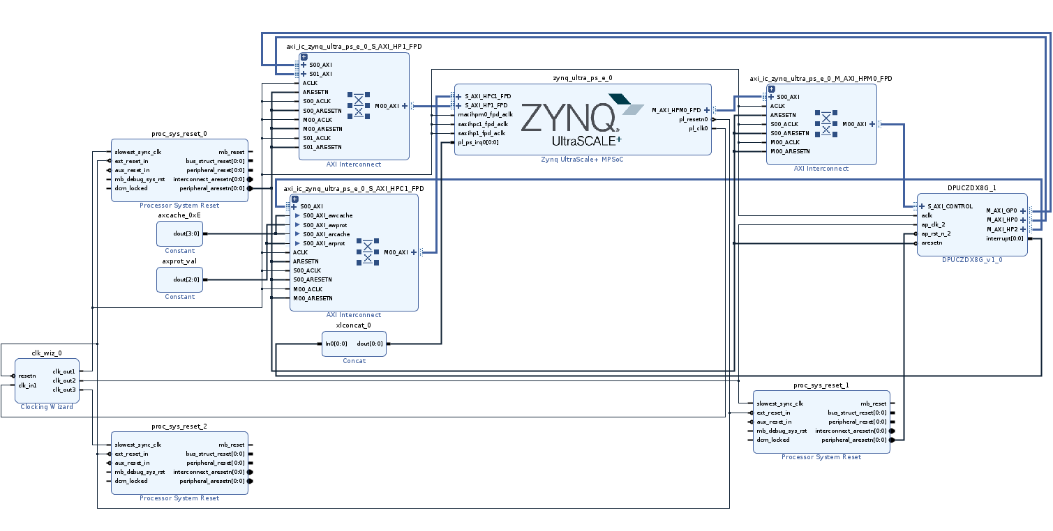
The design has 4 key components:
- Clocking Wizard: An IP for overclock or downclock a clock
- Processor System Reset: Two IPs in the design for resetting the DPU instance on every clock domain
- Concat: An IP for concatenating signals. In this case, you will use it as a bridge between DPU and Processing System
- DPU: the IP for AI models in FPGA
When in the following chapters we are going to describe the components needed in the hardware design, please take into account the structure highlighted in the previous scheme!
Step 1: Vivado Design
First, let me clarify what digital hardware design we will use as a base, which is the EDDP design by Xilinx (https://github.com/Xilinx/IIoT-EDDP ). MakarenaLabs is proud partner in developing Robotic Control solution with Xilinx, also for the new robotic platform KR260 ( https://www.xilinx.com/products/som/kria/kr260-robotics-starter-kit.html ) and also for EDDP project.
Secondly, we will need to open the design in Vivado. The design appears similar as follow (this is a part of it):
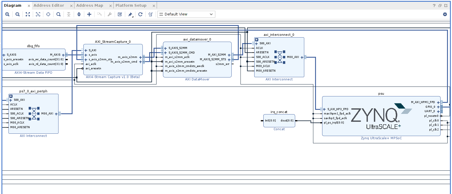
Example explanation
Our application has its own clock(s) domain(s), and its reset(s). In this case, we must use a clock of 100MHz, because the Vector Motor Control IP has a digital filter which order should change whether any modification to the clock occurs.
Unfortunately, the DPU has a particular approach when dealing with clock and reset domains. In fact, DPU has two clocks:
- The first one is for the data movement from the AXI interconnections (let’s suppose for simplicity that is 100MHz)
- Then, the second one is for compute internally the “Multiply ACcumulation” operations (MAC), and is double the data movement frequency, so according to the previous supposition, we need an input clock of 200MHz.
To create different clocks from a clock reference, we would use the IP “clocking wizard”, which takes in input a clock source and gives as an output the same one with a specific frequency set (example: 150MHz, 200MHz, 400MHz, 75MHz etc…).
So, you need to connect every output of the clocking wizard to its related domain processor reset. Let me give an example below:
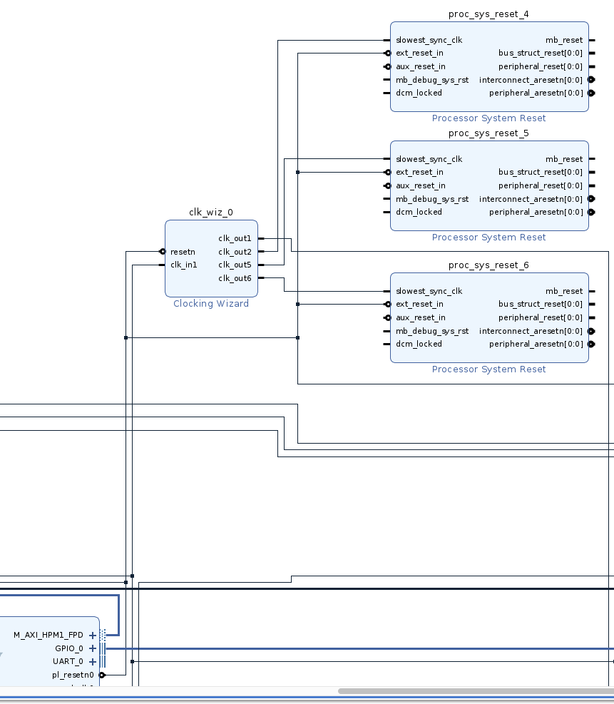
in-depth analysis of connections
There are three things to underline before moving on:
- There is a processor system reset for every clock in the output
- The external reset that we have connected to the processor system reset is the same of the clocking wizard
- One clocking wizard for multiple clocks in output, not just one
One important point to underline is that you must set as “low” the reset of the clocking wizard, not high. From the Processing System, the reset is idle when it’s high and active when it’s low.
By adding both Clocking Wizard and Processor System Reset, we are actually adding more domains on the clock and reset, which are going to be specific for what is related to the various clocks and resets needed from the DPU.
The other point that we want to add to our design is the “concat” IP. You can use his “concat” IP to connect the interrupt of the DPU to the Processor System, and thus the IP should be connected as follows:
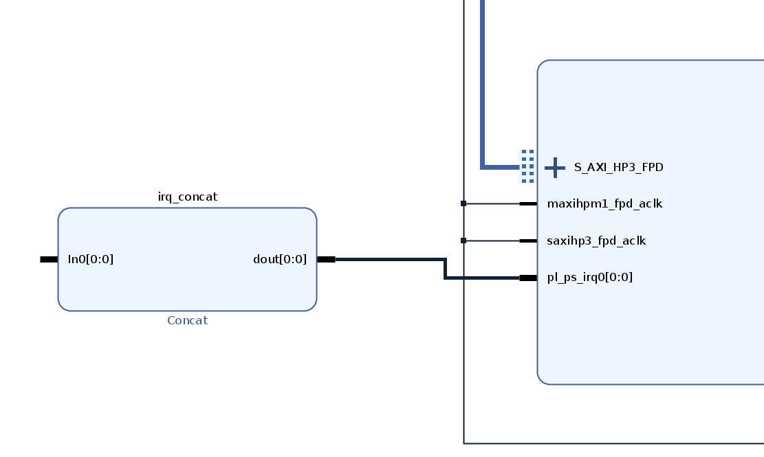
Then, you must left the “concat” IP with the input dangling and you must connect the concat output to the PL-PS interrupt request of the Processing System.
The dangling input is going to be the one used from the DPU to have an interrupt connection from the PL to the PS.
Now that we have set all the components needed to attach the DPU, we would need to create a platform to which we would connect the DPU.
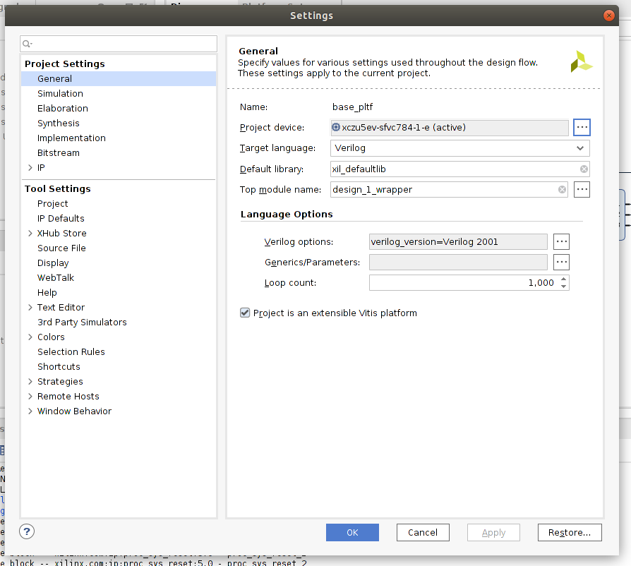
In Vivado, open “Settings” and tick the checkbox “Project is an extensible Vitis Platform” as in the figure below:
Exporting the platform
Now we have changed the nature of the project we are able to export a platform. Before exporting the platform we need to setup the interfaces and clock domains.
To setup the AXI ports we need to go to “Platform Setup” as in the following picture:
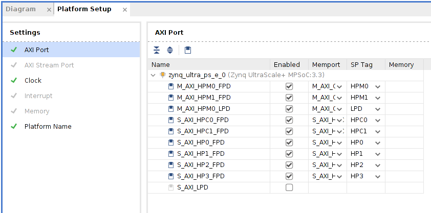
In the sub-menu “AXI Port” we enable with a tick in the box the ports we want and we give them a name in the “SP Tag” (this is very important!).
Secondly, in the sub-menu “Clock”, we need to select the clock we want to export and what is the base reference clock as in the following picture:
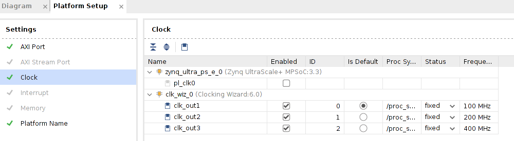
It is really important to enable the ones associated with the clocking wizard. We will set as a default the one with the lower clock, but nothing changes if you chose the other.
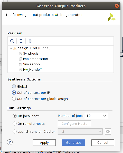
We are now ready to export the platform design, and thus we are going to tap on “Generate block design” in the left section of the block design of Vivado, exporting the modules “Out of context” as shown in the below figure:
Then we can tap “Export platform”. The options to tap for the export are “Hardware and Hardware Emulation” and then in the following page “Pre-Synthesis”. Now we find ourselves with a XSA file, that is a fixed hardware description out of which we would build our Vitis Platform.
Step 2: Vitis Platform Project
Finally we are now able to build our custom platform, which is compatible with the Vitis Flow for PYNQ DPU.
First of all, open a Vitis instance and tap “Create Platform Project”, it will show a window in which you can enter the name you prefer for the project, as in the below figure:
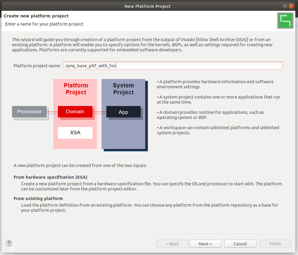
The name chosen of course can be whatever you prefer.
Secondly, we would need to select the XSA which we would build our Vitis Platform on top of it:
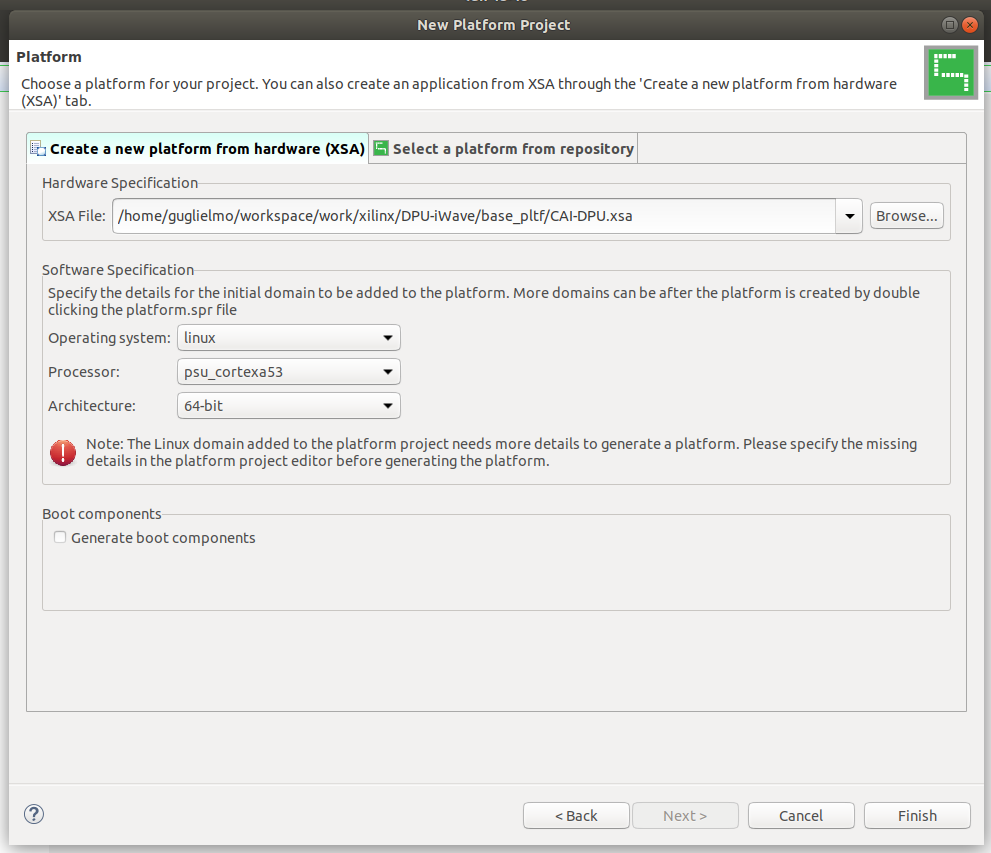
The XSA must be the one you exported at the end of the previous step of the Vivado design flow. Please note that the Operating System is linux and not standalone and that the Generate Boot Components option is disabled.
Once tapped Finish, we would need to build the project, by tapping the “hammer” icon as in the below figure:
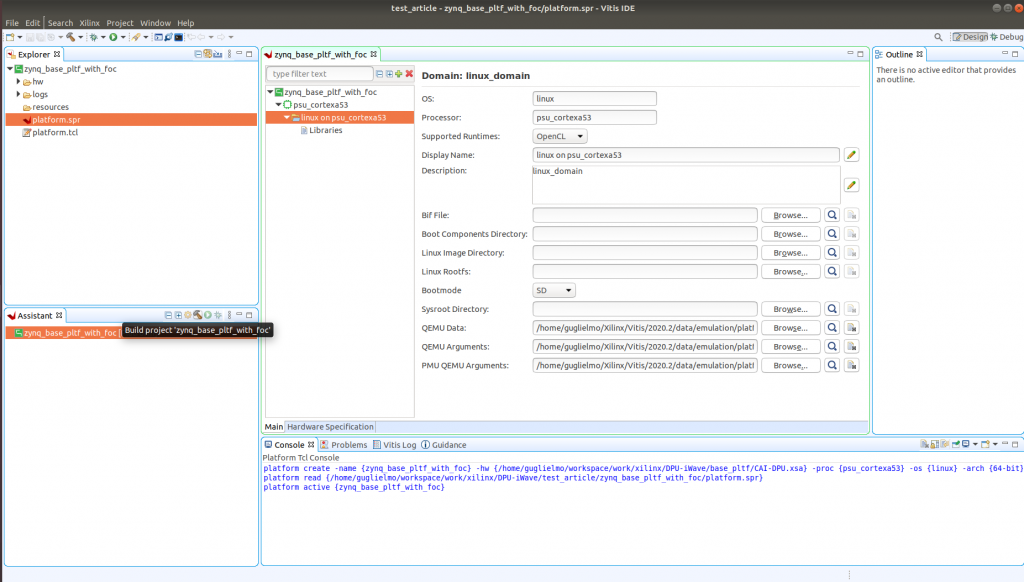
Don’t pay attention to the sections of linux_domain as the Pynq images have all the fields already provided.
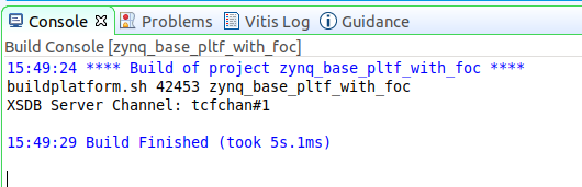
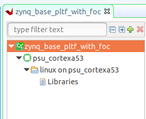
After the build is finished you will find a green tip on top of the platform name and the log as in the two figures which follows:
We are now ready to build the pynq-dpu design.
Step 3: PYNQ DPU Build
The last and final step is very simple. Download the repo of PYNQ DPU according to the instructions ( https://github.com/Xilinx/DPU-PYNQ ).
The you just need to tap “cd boards” into the repo, and build the platform on the specific board with a very simple command, shown in figure below but also on the repo, and then you are clear to go 😉
make BOARD=KV260 VITIS_PLATFORM=< vitis platform path >.xpfm
Pay attention to the config file of vitis inside the folder of the specific board (inside the boards folder), the names under the section connectivity in the file prj_config are the names of the AXI ports from the naming in the sub-section of creating the Vivado XSA.
Conclusion
We are now ready to try the Jupyter notebooks provided by the PYNQ team and run our AI model on top of them.
Now, you can do a lot of things with the platform created… but will be left to the reader for exploration 😜.