
PWM on PYNQ (part 2): controlling a Servo motor
Introduction
Welcome to part 2 of the previous article about PWM signals and PYNQ! In this article, we will show what is a servo motor and how to control a servo motor with the previous design of the PWM on the PYNQ framework, with a simple “recipe”. If you have missed the previous article, you can find it here!
So, let’s start!
What is a Servo Motor
A Servo Motor is a rotary actuator or linear actuator that allows for precise control of angular or linear position, velocity, and acceleration. Servomotors are used in applications such as robotics, CNC machinery, and automated manufacturing.
Servomotors are not a specific class of motor, although the term servomotor is often used to refer to a motor suitable for use in a closed-loop control system.
If you are curious about a servo motor and if you want to test it with a simple microcontroller (such as an Arduino), follow this simple tutorial.
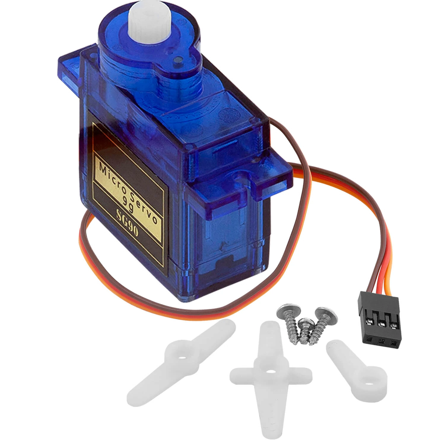
The most common servo motor, known by the hobbyists, is the SG90 Servo:
How it works a Servo Motor
We know you are curious, so let’s open it!
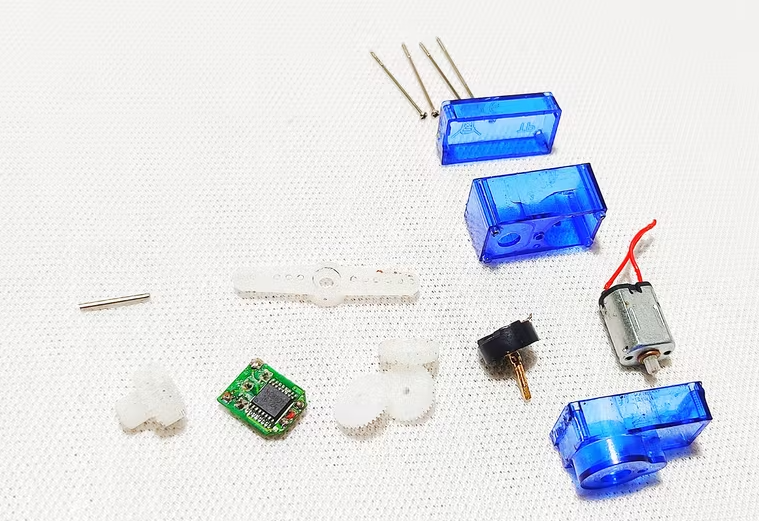
It contains a brushless motor, some gears that reduce the RPM of the motor but increase the torque, a circuit that interprets the external signal to a specific position of the rotor, and an “H bridge” that permits to rotate clockwise and counterclockwise.
So, this specific servo motor can’t simply rotate with a given voltage or current, but it needs a specific command in order to rotate to an angle. The command consists of a PWM signal that changes the period of the signal, the algorithm is the following:
- make a proportion in order to obtain the right value of 1 degree, so x = (20’000-4’000)/90; so 1 degree is equal to the value 178
- after that, obtain the period value using the desired angle multiplied by 178 (in order to convert it to the corresponding value) summed with 4’000
- finally, send the period and the pulse values to the corresponding registers of the Axi Timer.
The PYNQ code is the following:
def set_servo_angle(servo, angle):

    _period_ = angle * 178 + 4000
    _pulse_ = 90
    period = int((_period_ & 0x0ffff) *100);
    pulse = int((_pulse_ & 0x07f)*period/100);


    servo.write(TCSR0['address_offset'], temp_val_0)
    servo.write(TCSR1['address_offset'], temp_val_1)
    servo.write(TLR0['address_offset'], period)
    servo.write(TLR1['address_offset'], pulse)
Unfortunately, the reference voltage is 5V, so you need to power the motor with this voltage and you need also to control it with 5V. This might be a problem with an FPGA because the reference voltage is 3,3V or 1,8V, but we can break the law with a supplementary circuit.
Use PWM on PYNQ
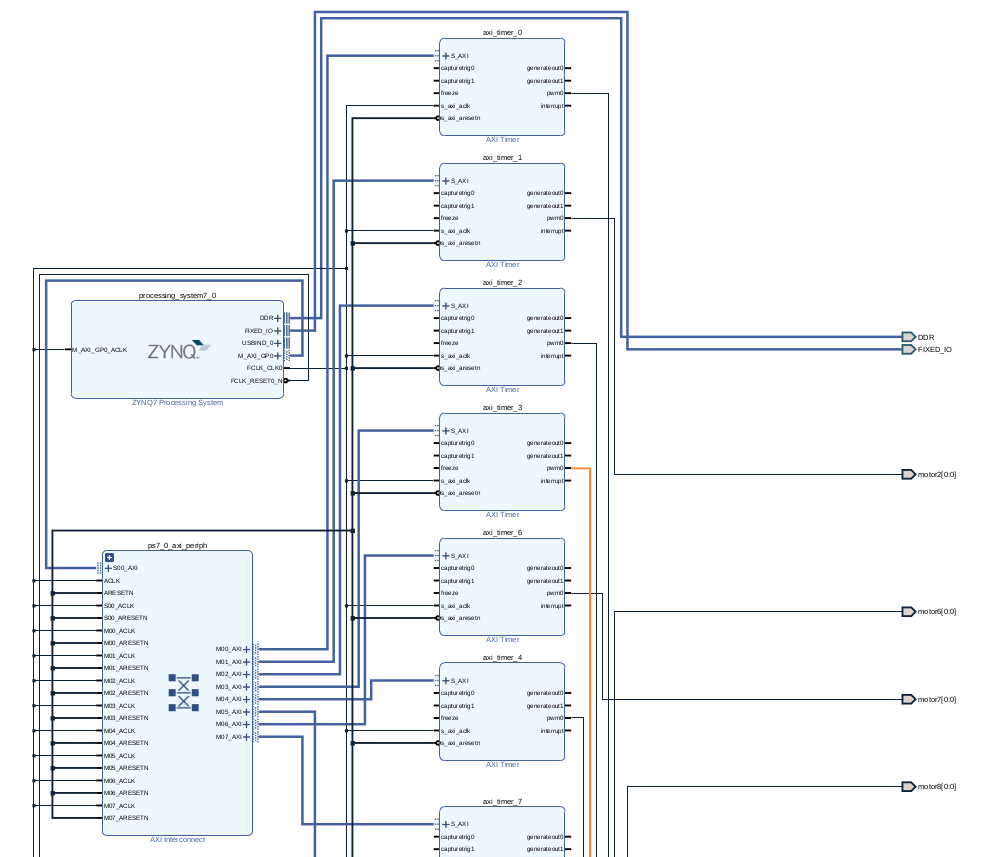
So, let’s recreate the PWM Design in Vivado (it is the same of the previous article):
After the generation of the bitstream file, we need to make a simple circuit that can “drive” the motor with the right voltage.
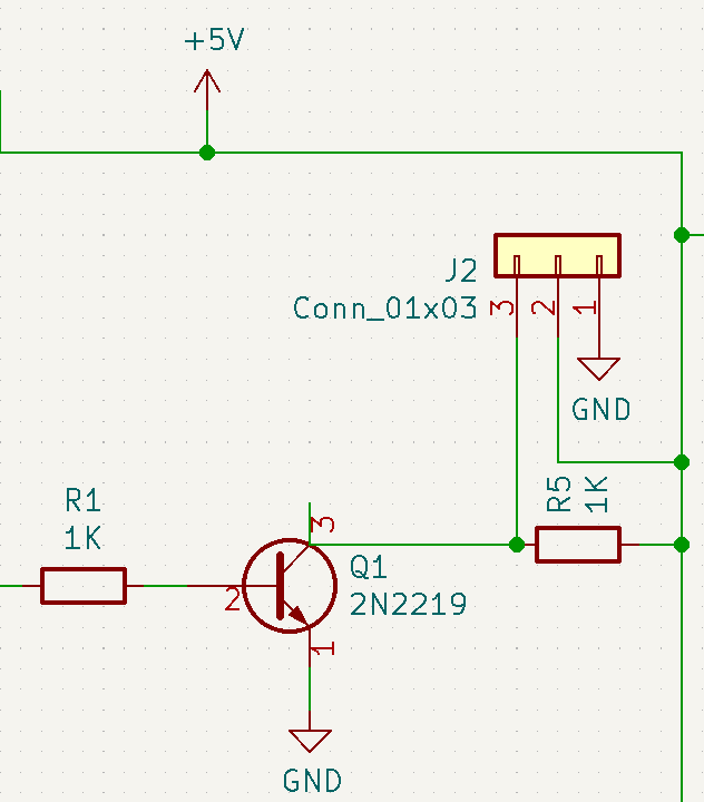
In order to do that, we need to use a simple NPN circuit that operates as a physical switch:
- the PWM is connected to the base of the transistor, the collector is connected to the output of the circuit and to a resistor that is connected to the 5V, and the emitter is connected to the ground
- the current passed through the collector and through the emitter of the transistor
- when the base of the transistor is not alimented, the 5V passed through the resistor and the output is 5V
- when the base of the transistor is alimented, the current is pulled down so the output is 0V
You can use any NPN transistor for this purpose, for example, BC337.
This is an example of the circuit design:
If you are not familiar with the NPN circuit, we suggest this good tutorial:
https://www.electronics-tutorials.ws/transistor/tran_4.html
So, let’s connect all together and let’s create a simple PYNQ code for testing all:
from pynq import Overlay

def set_servo_angle(servo, angle):

    _period_ = angle * 178 + 4000
    _pulse_ = 90
    period = int((_period_ & 0x0ffff) *100);
    pulse = int((_pulse_ & 0x07f)*period/100);


    servo.write(TCSR0['address_offset'], temp_val_0)
    servo.write(TCSR1['address_offset'], temp_val_1)
    servo.write(TLR0['address_offset'], period)
    servo.write(TLR1['address_offset'], pulse)


ol = Overlay("pwm.bit")
motor0 = ol.axi_timer_0
TCSR0 = ol.ip_dict['axi_timer_3']['registers']['TCSR0']
TCSR1 = ol.ip_dict['axi_timer_3']['registers']['TCSR1']
TCSR0_address = TCSR0['address_offset']
TCSR1_address = TCSR1['address_offset']
TCSR0_register = TCSR0['fields'] # bit_offset for address
TCSR1_register = TCSR1['fields']
TLR0 = ol.ip_dict['axi_timer_3']['registers']['TLR0']
TLR1 = ol.ip_dict['axi_timer_3']['registers']['TLR1']
TLR0_address = TLR0['address_offset']
TLR1_address = TLR1['address_offset']
# The mode for both Timer 0 and Timer 1 must be set to Generate mode (bit MDT in the TCSR set to 0)
temp_val_0 = 0
temp_val_1 = 0
# The PWMA0 bit in TCSR0 and PWMB0 bit in TCSR1 must be set to 1 to enable PWM mode.
temp_val_0 = set_bit(temp_val_0, TCSR0_register['PWMA0']['bit_offset'])
temp_val_1 = set_bit(temp_val_1, TCSR1_register['PWMA1']['bit_offset'])
# The GenerateOut signals must be enabled in the TCSR (bit GENT set to 1). The PWM0
# signal is generated from the GenerateOut signals of Timer 0 and Timer 1, so these
# signals must be enabled in both timer/counters
temp_val_0 = set_bit(temp_val_0, TCSR0_register['GENT0']['bit_offset'])
temp_val_1 = set_bit(temp_val_1, TCSR1_register['GENT1']['bit_offset'])
# The counter can be set to count up or down. UDT
temp_val_0 = set_bit(temp_val_0, TCSR0_register['UDT0']['bit_offset'])
temp_val_1 = set_bit(temp_val_1, TCSR1_register['UDT1']['bit_offset'])
# set Autoreload (ARHT0 = 1)
temp_val_0 = set_bit(temp_val_0, TCSR0_register['ARHT0']['bit_offset'])
temp_val_1 = set_bit(temp_val_1, TCSR1_register['ARHT1']['bit_offset'])
# enable timer (ENT0 = 1)
temp_val_0 = set_bit(temp_val_0, TCSR0_register['ENT0']['bit_offset'])
temp_val_1 = set_bit(temp_val_1, TCSR1_register['ENT1']['bit_offset'])
print("set bit values of registers for LogiCORE PWM")

set_servo_angle(motor0, 90)
If everything works, you can see your motor that rotates to 90 degrees. Pretty cool, right? 😎
Conclusions
Today we have seen how to use a PWM design for PYNQ with a specific servo motor application. If you are interested in the implementation of a different motor or if you want to go into details in this design or in a different design, don’t hesitate to comment on the article!

[…] take a look at the servo motor project on PYNQ: PWM on PYNQ (part 2): controlling a Servo motor […]