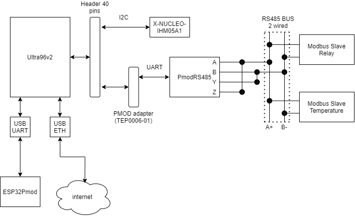
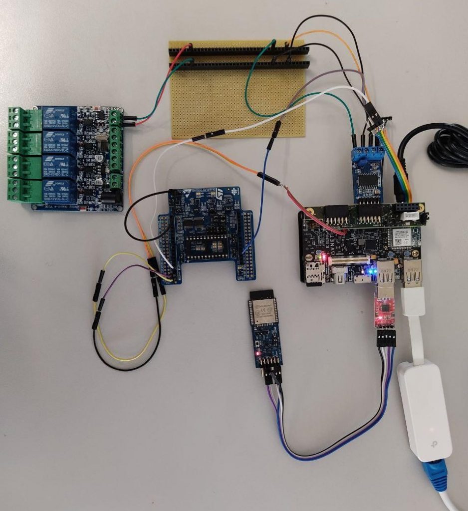
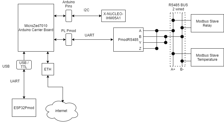
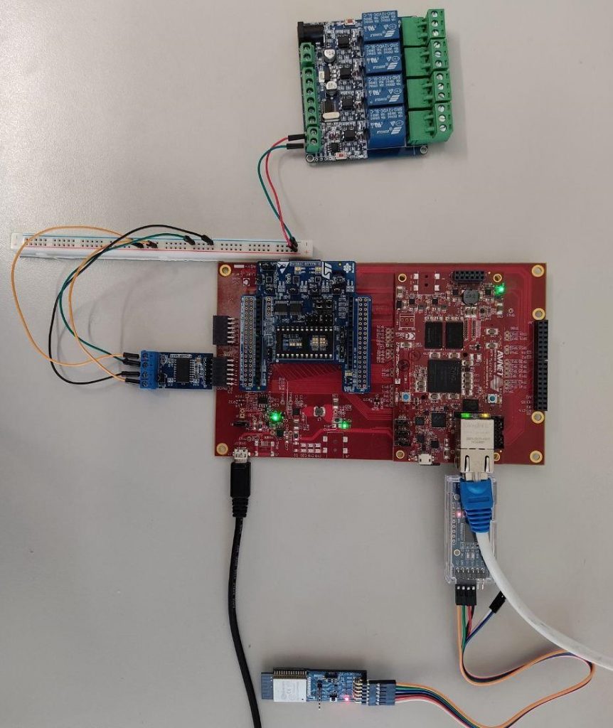
SMART-IO: engineer an IoT on Edge solution

Abstract

This article explains how to engineer an IoT on Edge solution, a multisensor scenario with a wide range of communication protocols. So, the solution proposed, called SMART-IO, is about an implementation of the complete stack to satisfy hardware and software requirements. Then, the engineering samples proposed is a unique System On Module (SOM) or MultiProcessor System On Chip (MPSoC) solution. They are based on Xilinx Zynq family, which allows to manage a high data throughput and low latency when it comes to data processing.

Statement of the problem

The evolution of IoT to modern days has enlightened the necessity of complex hardware solutions that satisfy the high throughput of data coming from the sensor. This is important for the data processing, because it is needed low latency where the data is collected, in order to avoid massive data transfer to the cloud server. Then, the hardware must not be able just to manage some network or sensor interfaces, but also to provide a high compute capability

The cloud services chosen for this project are Microsoft Azure services. In particular, Azure is a cloud computing service which offers to the end-user a wide range of services.

So we choose two FPGA boards, the Microzed 7010 plus Arduino Carrier Board and the Ultra96, both based on the Zynq family. The first board is a SOM, with Carrier board extending the Microzed interfaces, and it is part of the Zynq-7000 family. The second board is a MPSoC, part of the Zynq UltraScale+ family. The Programmable Logic (PL) of the board has been mainly used for the embedded of the project. Also, having the I/O managed by the PL, it becomes very easy to integrate machine learning algorithms in the process. So, these are the baseline of the development of SMART-IO solution.

Physical Architecture of SMART-IO

Now we dig a little bit in the architecture details, explaining the hardware and software stack used. Here below a simple view of the setup.

System Architecture for Ultra96 SMART-IO
System Architecture for Ultra96

Ultra96v2

The Ultra96V2 board represents the main component in this SMART-IO project. It is responsible for both intra/inter-net events management.

The board has two main components: the Processing System and the Programmable Logic.

The PS part (CPU) manages the internet connection and the backend/frontend part, while the PL part (FPGA) manages directly the I/O and the data collection from the sensor. 

So you can connect to the board with two different interfaces. The first interface is ethernet and is directly accessible on Ultra96v2. The wifi interface is provided by an external module of ESP-IDF

The  PMOD adapter grant the communication between the ESP and Ultra96.   

Finally, we have the PMOD adapter TEP00006-001, which converts the 40 header pins of the Ultra96 into 3 PMODs. One of the PMOD communicates with the Modbus PMOD, using UART protocol. The I2C use the already candidate pins, according to Ultra96V2 documentation. 

Here below the physical setup.

Physical Setup of the board SMART-IO
Physical Setup of the board

Microzed 7010

For the Microzed 7010 board, we used the same architecture.

System Architecture for Microzed 7010 SMART-IO
System Architecture for Microzed 7010

As you can see, the structures are really similar to each other. The PS manages internet connection and backend/frontend, whereas the PL manages the I/O from peripherals and data manipulation. Here below the physical setup of Microzed.

Physical setup of Microzed SMART-IO
Physical setup of Microzed

Hardware Architecture of SMART-IO

The PL side of the boards had been reconfigured in order to be interfaced with the various pins and communication protocols. The process was done using the GUI interface of Vivado and worked directly on the block design using the Xilinx LogiCORE suites. 

The LogiCORE suite offers blocks which already implement the protocols needed for this project, or rather, I2C, UART and a block for GPIO management. 

Then, to connect all the blocks with the board and between themselves, we used the AXI interconnection, a gold standard protocol of communication used in hardware. 

Finally, to set the pins for I/O peripheral data management we set the constraint file to interface the pins to the block which implement their communication protocol respectively.

Here the block design for ultra96 of SMART-IO with its constraints.

 
Block Design of Vivado for Ultra96 SMART-IO
Block Design of Vivado for Ultra96
Constraints of Vivado for Ultra96v2
Constraints of Vivado for Ultra96
Addresses of Vivado for Ultra96

Here the block design for Microzed7010 of SMART-IO with its constraints:

Block Design of Vivado for Microzed 7010 SMART-IO
Block Design of Vivado for Microzed 7010
Constraint of Vivado for Microzed 7010
Addresses of Vivado for Microzed 7010

Software Architecture of SMART-IO

This part is managed by the Processing System (PS). This part has to manage the internet/cloud connection, the access point provided by the ESP32 and the demonized processes by PM2.
Everything except the frontend, which is based on NodeJS, Python is the main code.
To interface the PL side it was chosen to use a python framework called PYNQ. This library allows the user to simply access the PL side using very simple Python calls. PYNQ also allows to integrate hardware functions in software projects, like this one. 

Link: http://www.pynq.io/

Software design

The processes can be divided in three sections:

  1. Backend server: we built a little Flask server, which receives GET and POST methods to send or receive some information. The server stores the current state of the configuration of the sensors every time there is a POST in a JSON file. This last job is very important in offline configuration to update the frontend.
  2. Communication with Azure: in the configuration is fundamental to exchange data with the cloud. In particular, if the board is online, there are two processes, one for sending data and one for receiving the data from the cloud.
  3. Frontend: this part is related to the user experience, so we built an interface which aims to be together the as most easy to use as possible.

Finally, we create two types of interfaces, one for the offline portion and one for the online portion, both of them with a login homepage.

Online dashboard interface SMART-IO
Online dashboard interface
Offline dashboard interface SMART-IO
Offline dashboard interface

If you need to go into details about the hardware design, please read this article.