Bare-metal From PYNQ: the full guide
Introduction
We have seen a lot of projects made with the PYNQ framework. But now? How we can create a real product with those projects? With this article, we will see a simple guideline for transforming a Proof of Concept project made with PYNQ into a real product, using a bare-metal system.
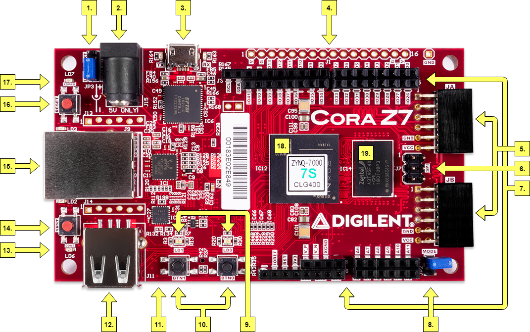
For this tutorial, we will use a Cora Z7 board from Digilent.
What is a bare-metal system?
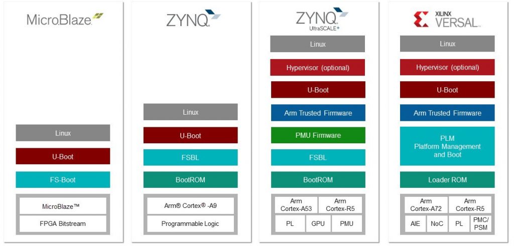
A bare-metal system on an FPGA refers to the implementation of a hardware or software system directly on the FPGA fabric without the need for an operating system. This means that the system code is the only code running on the hardware, with no intermediate software layer. This design has several advantages over traditional systems that rely on an operating system.
One of the benefits of a bare-metal system on an FPGA is the reduced complexity of the design. With no operating system, there are fewer layers of abstraction, making the system more straightforward to understand and troubleshoot. This simplicity also leads to faster and more efficient operation, as there is no overhead from an operating system.
Another advantage of a bare-metal system on an FPGA is security. By removing the operating system, you can mitigate potential vulnerabilities associated with the software. This makes the system more resistant to attacks and ensures that it operates consistently and predictably.
Finally, you can customize a bare-metal system on an FPGA to meet specific requirements. With no operating system, you can tailor the entire system to the specific needs of the application. This level of customization leads to better performance and more efficient use of system resources. In summary, a bare-metal system on an FPGA is a powerful tool that offers simplicity, security, and customization.
Why PYNQ can help construct a bare-metal production system?
PYNQ is a powerful tool for starting to construct a bare-metal production system. With PYNQ, you can test your project in an easy language like Python. This is a significant advantage because Python is relatively simple to use and has a vast array of libraries and frameworks to work with. With Python, you can write code quickly and efficiently, and avoid common programming mistakes.
PYNQ can also help you avoid mistakes when building your system. It provides a set of predefined functions and modules that you can use to program your design. This ensures that you are using best practices, and that you can structure your design in a well-organized way. Additionally, PYNQ provides a set of tools for debugging and monitoring your system. This can help you to identify and fix issues before they become a problem.
One of the most significant benefits of using PYNQ is that it can accelerate your productivity. With PYNQ, you don't need to compile your code every time you make a change. This can be a huge time saver, especially if you are working on a large project. Instead, you can test your software without any compilation delay, which means you can see the results of your changes almost immediately.
Another advantage of using PYNQ is that it provides access to the FPGA's hardware resources. This allows you to create optimized designs for performance and efficiency. This can significantly improve the performance of your system, and allow you to handle more data processing tasks.
Let's start! The servo motor project
Let's take a look at the servo motor project on PYNQ: PWM on PYNQ (part 2): controlling a Servo motor .
In this design, we have instantiated some "Axi Timer" IPs and we have connected the PWM output to the physical pins of the PYNQ Z2. We only need to change the board reference in Vivado to the CoraZ7 and use the custom PYNQ image for the board. You can find the pins definition here: https://digilent.com/reference/lib/exe/fetch.php?tok=a49a20&media=https%3A%2F%2Fgithub.com%2FDigilent%2Fdigilent-xdc%2Farchive%2Fmaster.zip
Have you missed our announcement of the CoraZ7 porting of PYNQ?
Assuming that you have followed all the instructions in the previous article, we are ready to create a bare-metal project.
Step 1: export Hardware for the bare-metal project
In the Vivado project, after the bitstream generation, you need to export the hardware definition.
To export the hardware design, click File → Export → Export Hardware in the File menu.
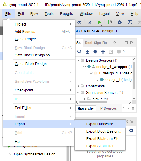
Follow the wizard and remember to click to "Include bitstream" during the wizard flow. The Files screen gives you the option to choose a name for the Xilinx Shell Architecture (XSA) file, and provides a path to a folder where the file will be placed. Give your XSA file a name, and choose a memorable location to place it in. This file will later be imported into Vitis, so take note of where it is placed and what it is called. Remember: do not use spaces in the file name or in the path!
Step 2: Create a Vitis project for bare-metal
Now we need to create an Application project, which is the software that will run on the microprocessor of the FPGA (the PS side).
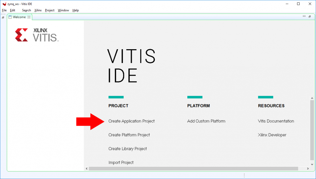
So, open Vitis and click to "Create Application Project"
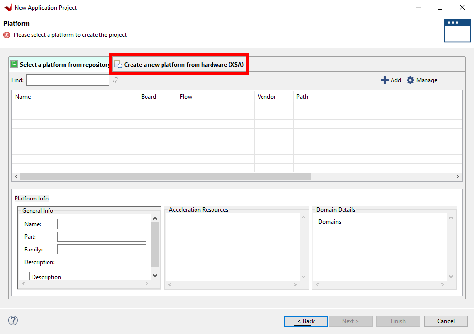
Then, Vitis needs to know how is structured the hardware that will run on the FPGA, so we need to create a platform. To do that, in the next wizard step, you need to select the tab "Create a new platform from hardware (XSA)" and select from your filesystem the previously generated file.
Then, you need to select where the software application will run (of course, the microprocessor). In the next wizard step, select "ps7_cortex9_0".
Next, the domain in which the application project operates will be defined. In this case, all default settings will be used. Here, you can select also the operating system ("standalone" or "freeRTOS"). For this tutorial, select "standalone". Click Next to continue.
Finally, you can select a template project. The template project will be defined according to your platform, especially for the peripherals. So, select "Peripheral tests" to test your design and also to get familiar with the peripheral configuration and usage. Click Next for starting programming!
Step 3: Create your bare-metal application
Your main application is in the file "peripheral.c".
Let's take a look at the file:
{
int status;

print("\r\n Running TmrCtrSelfTestExample() for axi_timer_0...\r\n");

status = TmrCtrSelfTestExample(XPAR_AXI_TIMER_0_DEVICE_ID, 0x0);

if (status == 0) {
print("TmrCtrSelfTestExample PASSED\r\n");
}
else {
print("TmrCtrSelfTestExample FAILED\r\n");
}
}
As you see, there are a lot of pre-structured functions that help you in the software design. In particular, the "TmrCtrSelfTestExample" function is defined in "xtmrctr_selftest_example.c" file and is designed as follows:
int TmrCtrSelfTestExample(u16 DeviceId, u8 TmrCtrNumber)
{
int Status;
XTmrCtr *TmrCtrInstancePtr = &TimerCounter;

/*
* Initialize the TmrCtr driver so that it iss ready to use
*/
Status = XTmrCtr_Initialize(TmrCtrInstancePtr, DeviceId);
if (Status != XST_SUCCESS) {
return XST_FAILURE;
}

/*
* Perform a self-test to ensure that the hardware was built
* correctly, use the 1st timer in the device (0)
*/
Status = XTmrCtr_SelfTest(TmrCtrInstancePtr, TmrCtrNumber);
if (Status != XST_SUCCESS) {
return XST_FAILURE;
}

return XST_SUCCESS;
}
In particular, takes into input the device ID (in the previous software block, is XPAR_AXI_TIMER_0_DEVICE_ID) and the timer count (in the previous block, 0 is the first Timer defined in the design).
We need only a new function for PWM generation. This function can be found in the software-embedded repository in the Xilinx Github.
#define PWM_PERIOD 2000000 /* PWM period in (500 ms) */
#define TMRCTR_0 0 /* Timer 0 ID */
#define CYCLE_PER_DUTYCYCLE 10 /* Clock cycles per duty cycle */
#define MAX_DUTYCYCLE 100 /* Max duty cycle */
#define DUTYCYCLE_DIVISOR 4 /* Duty cycle Divisor */
#define WAIT_COUNT PWM_PERIOD /* Interrupt wait counter */

int TmrCtrPwmExample(XScuGic *IntcInstancePtr, XTmrCtr *TmrCtrInstancePtr,
u16 DeviceId, u16 IntrId, u8 duty_cycle)
{
u8 DutyCycle;
u8 Div;
u32 Period;
u32 HighTime;
int Status;

/*
* Initialize the timer counter so that it's ready to use,
* specify the device ID that is generated in xparameters.h
*/
Status = XTmrCtr_Initialize(TmrCtrInstancePtr, DeviceId);
if (Status != XST_SUCCESS) {
return XST_FAILURE;
}


/*
* We start with the fixed divisor and after every CYCLE_PER_DUTYCYCLE
* decrement the divisor by 1, as a result Duty cycle increases
* proportionally. This is done until duty cycle is reached upto
* MAX_DUTYCYCLE
*/
Div = DUTYCYCLE_DIVISOR;

/* Fail check for 0 divisor */
if (!Div) {
Status = XST_FAILURE;
return Status;
}

/* Disable PWM for reconfiguration */
XTmrCtr_PwmDisable(TmrCtrInstancePtr);

/* Configure PWM */
Period = PWM_PERIOD;
HighTime = duty_cycle * PWM_PERIOD / 100;
DutyCycle = XTmrCtr_PwmConfigure(TmrCtrInstancePtr, Period,
HighTime);
if (Status != XST_SUCCESS) {
Status = XST_FAILURE;
return Status;
}

xil_printf("PWM Configured for Duty Cycle = %d\r\n", DutyCycle);

/* Enable PWM */
XTmrCtr_PwmEnable(TmrCtrInstancePtr);


return Status;
}
As you can see, you can set the period and duty cycle according to your desiderata.
So, add in the main function the function call to see the PWM in the output connected to the Timer 0:
{

XTmrCtr ps7_scutimer[16];
XScuGic intc;

int status;

print("\r\n Running TmrCtrSelfTestExample() for axi_timer_0...\r\n");

status = TmrCtrSelfTestExample(XPAR_AXI_TIMER_0_DEVICE_ID, 0x0);

if (status == 0) {
print("TmrCtrSelfTestExample PASSED\r\n");

TmrCtrPwmExample(&intc, &ps7_scutimer, XPAR_AXI_TIMER_0_DEVICE_ID, XPAR_PS7_SCUTIMER_0_INTR, 0);
}
else {
print("TmrCtrSelfTestExample FAILED\r\n");
}
}
... a piece of cake 🙂
Finally, you can add your code according to the PYNQ program that you have defined in the PYNQ project. Remember to convert Python code to C code!
Step 4: compile and deploy the bare-metal software
Now, you are ready to compile the software!
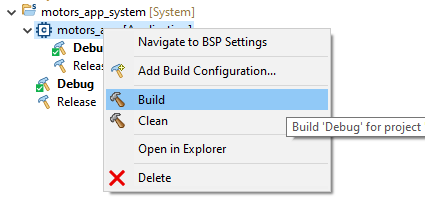
Right-click in the bottom-left tab and select "Build".
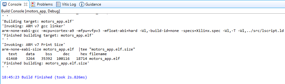
After, a while, you will see in the console tab the success notification.
Now you can choose to test your application (and debug it as normal software) by clicking on the debug icon in the top select bar of Vitis. You will test the application directly to the board, so remember to attach the board via USB and select the boot mode as USB (removing the jumper number 8).
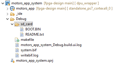
If everything is working as expected, you can deploy the application. To do that, you need an SD Card formatted as FAT32.
Once you have an SD Card, simply add the file "BOOT.BIN" file generated in your project. You will find the file in <your project>_app_system → Debug → BOOT.BIN