PYNQ and floppy driver how to play music
Introduction
Are you tired of the same old boring music-making methods? Well, get ready to rock your socks off with the latest tech tutorial we've got for you! In this article, we're going to show you how to use the power of the PYNQ framework on an FPGA to create sick beats using a simple floppy drive.
Yes, you read that right. It's time to break out the floppy disks and dust off your old collection because we're about to unleash the potential of this classic tech to create something truly unforgettable. So get ready to mix it up and bring a whole new level of fun to your music-making experience. It's time to dive into the wild world of FPGA music-making with PYNQ!
What is a floppy drive?
A floppy drive is an ancient device of the Stone Age of computing. It was like a small, flat, plastic disk that held approximately 1.44 megabytes of data. You could store all of your important files on this piece of dusty technology if you didn't mind waiting for 45 minutes for it to read or write data. Think of it like a snail carrying a backpack full of information, only slower. Nowadays, the floppy drive has gone the way of the dinosaurs and VHS tapes. But if you ever come across a floppy drive, treat it with respect and nostalgia, and maybe even shed a tear for the good old days.
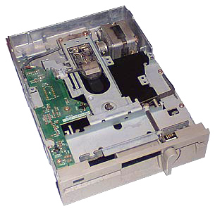
A floppy drive consists of several components, including:
- Drive motor - this powers the spinning of the disk to enable data access.
- Read/write head - this is the component responsible for reading and writing data onto the magnetic disk.
- Head actuator - this is the mechanism that moves the read/write head to the appropriate location on the disk.
- Spindle - this is the central axis around which the floppy disk rotates.
- Disk controller - this is the electronic circuit board that sends and receives signals to and from the read/write head.
- Power supply - this provides the necessary power to the floppy drive to operate the components.
- Ribbon cable - this connects the floppy drive to the motherboard or controller card.
- Housing - this is the case that surrounds the internal components and provides a stable, protective enclosure for the floppy drive.
Together, these components enable a floppy drive to read and write data onto a 3.5-inch floppy disk.
Why the floppy drive is so noisy?
A floppy drive made a noise because of the way it read and wrote data to the floppy disk. The drive used a read/write head to access the data on the disk, and this head needed to move back and forth across the surface of the disk to read or write information. As it did so, it made a distinctive clicking noise that many people associate with floppy drives.
In addition to this clicking noise, floppy drives also made other sounds as they loaded disks or accessed particular sectors of the disk. These sounds were produced by the gears and motors inside the drive as they spun the disk and moved the read/write head.
Overall, the noise produced by a floppy drive was a result of the mechanical nature of their operation. While newer technologies like solid-state drives are much quieter, the noise of a floppy drive remains an iconic sound of computing history.
Music with a floppy drive
Some musicians have taken a trip down memory lane and dusted off their old floppy drives to create some hilarious jams. Who knew that these outdated pieces of technology could actually produce some sick beats?! Move over Mozart – it's time to make way for the floppy disk maestros!
But why? Here are some considerations:
- Uniqueness: The limited capabilities of the floppy disk drive, allowed musicians to create unique sounds
- Hackability: Floppy drives could be easily modified and repurposed to create new and unusual sounds
- Nostalgia: For many musicians who grew up in the 1980s and 1990s, floppy disks were a familiar and nostalgic part of their childhood
- Experimental: Floppy disks offered a unique platform for experimental musicians to create glitchy, distorted, and unpredictable sounds
- DIY Culture: the musicians can create their own instruments and equipment to produce music that was individualistic and personal.
Here are some examples:
PYNQ and floppy drive
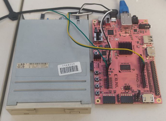
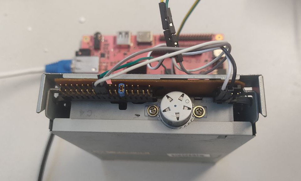
So, let's make some noise! We will use the PYNQ base bitstream and the famous PYNQ Z2 board. For this purpose, we need to implement those simple facts:
- you can generate a sound with a "vibration"
- the floppy drive has a stepper motor that controls the position of the magnet for read/write operations
- we need to find a way to control the stepper motor in order to create a vibration
- the pitch of a specific note corresponds to the "velocity" of the vibration of the stepper motor
Let's take a look at a common floppy drive pinout:
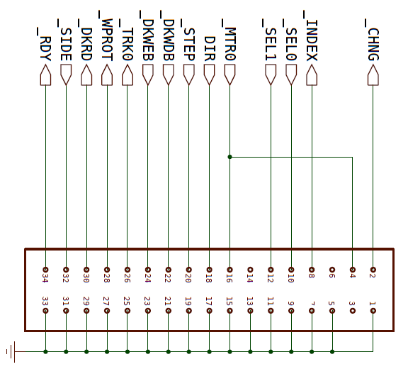
We can see that there are 2 pins that can help us to achieve our job:
- The "direction" pin gives the information to the floppy driver in which direction the stepper motor will go
- the step pin pushes the motor to the next position (regarding its direction)
So, according to that, we need to continuously change the values of those pins! So we will connect the AR8 to the step pin and the AR9 of the PYNQ Z2 to the direction pin.
The control of the stepper motor needs to be extremely precise, so we will try 2 approaches: a PS-PL approach and a Microblaze approach.
If you need to know more precisely how to control PYNQ, GPIO, and Microblaze, take a look at the GPIO article and Microblaze article.
PYNQ code for PS-PL approach
One approach to using the Programmable System (PS) and Programmable Logic (PL) in Xilinx FPGAs is for the PS to act as the master and send individual values to the PL while having direct control over the PL. So, we have got the code from a public tutorial for Raspberry PI here and ported it to the PYNQ framework:
from pynq.overlays.base import BaseOverlay
from pynq.lib.arduino import Arduino_IO
# Define an octave with naturals and sharps (Zz = rest)
Cn = 1
Cs = 2
Dn = 3
Ds = 4
En = 5
Fn = 6
Fs = 7
Gn = 8
Gs = 9
An = 10
As = 11
Bn = 12
Zz = 13

# Define another one with flats and remaining sharps
Bs = 1
Df = 2
Dn2 = 3
Ef = 4
En2 = 5
Es = 6
Gf = 7
Gn2 = 8
Af = 9
An2 = 10
Bf = 11
Bn2 = 12
Zz2 = 13
base = BaseOverlay("base.bit")
arduino_pin_d8 = Arduino_IO(base.ARDUINO, 8, 'out')
arduino_pin_d9 = Arduino_IO(base.ARDUINO, 9, 'out')
dirPin = arduino_pin_d8
stepPin = arduino_pin_d9
# Frequencies in hundredths of Hz, e.g. middle A = 44000
# 4 Octaves with 12 notes per octave, i.e. C to B
freq = [[13081,13859,14683,15556,16481,17461,18500,19600,20765,22000,23308,24694],
[26163,27718,29366,31113,32963,34923,36999,39200,41530,44000,46616,49388],
[52325,55437,58733,62225,65925,69846,73999,78399,83061,88000,93233,98777],
[104650,110873,117466,124451,131851,139691,147998,156798,166122,176000,186466,197553]]
# Frequency (in Hz) is converted to Floppy Delay using the formula:
#   314000 / frequency = floppy delay
# so middle A = 314000 / 440 = 714
#
# Lowest realistic note is delay = 1550
# Highest realistic note is delay = 210
floppyConv = 31400000
# Calculate all our floppy delays at the start
floppyDelay = [[0 for j in range(12)] for i in range(4)]
def _resetMotor():
# To reset head position move back 10 then forward 5
dirPin.write(0)
for i in range(10):
stepPin.write(1)
stepPin.write(0)
time.sleep(0.001)
dirPin.write(1)
for i in range(5):
stepPin.write(1)
stepPin.write(0)
time.sleep(0.001)
time.sleep(0.4)
def _init():
_resetMotor()
for octave in range(4):
for note in range(12):
floppyDelay[octave][note] = floppyConv / freq[octave][note]
import time
def millis():
return round(time.time() * 1000)
def delayMicroseconds(seconds):
time.sleep(seconds/1000000.0)
def _playNote(note, octave, length):
if note == Zz:
time.sleep(length/1000)
return
_dir = 1
pause = floppyDelay[octave][note] * 10
endTime = millis() + length
while (millis() < endTime):
#while(noteStatus):
dirPin.write(_dir)
if _dir == 0:
_dir = 1
else:
_dir = 0
stepPin.write(1)
stepPin.write(0)
delayMicroseconds(pause)
def _rest(length):
endTime = time.time() + length/1000
while time.time() < endTime:
time.sleep(0.005)
_init()
Ok, now let's play the famous Super Mario theme!
# super mario: EE E CE G -G
_playNote(Es, 2, 25)
_rest(80)
_playNote(Es, 2, 20)
_rest(200)
_playNote(Es, 2, 25)
_rest(200)
_playNote(Cs, 2, 20)
_rest(80)
_playNote(Es, 2, 25)
_rest(250)
_playNote(Gs, 2, 25)
_rest(600)
_playNote(Gs, 1, 25)
Uhm... This music is like a cat running across a piano... it's a chaotic mess that only adds confusion to an already confusing world. What's the problem?
Controlling GPIOs from PS in FPGAs, in this case, is not a good idea, because it can lead to timing and synchronization issues. The communication between PS and PL is done through an AXI interface, which has certain latencies and delays. This can cause delays in updating the GPIO values, leading to incorrect outputs or unpredictable behavior. Furthermore, using PS to control GPIOs reduces the flexibility of the FPGA as it limits the number of available GPIOs and reduces the bandwidth available for other functions. It is therefore recommended to use the programmable logic fabric to control GPIOs for more efficient and reliable performance. In addition, in this case, we are running our code on an operating system, so the timing of the GPIOs writes is completely unpredictable.
PYNQ code for Microblaze approach
Ok, so we need to find a way to convert our code. We need to make it more stable and predictable. Fully PL device control with Vitis HLS? No, it is not effortless and we can't use the base bitstream. We need only to implement a sort of device driver. So, the best idea is to implement the code on a MicroBlaze.
An innovative feature of the latest PYNQ releases is to implement, compile and deploy directly on a Jupyter Notebook the MicroBlaze code. You can take a look at this PYNQ workshop that shows how to use a MicroBlaze via Jupyter Notebook.
So, let's implement the Jupyter Notebook!
%%microblaze base.ARDUINO
#include <pyprintf.h>
#include "gpio.h"
#include <unistd.h>
#include <time.h>
#include <timer.h>
gpio dirPin;
gpio stepPin;
// Define an octave with naturals and sharps (Zz = rest)
enum { Cn, Cs, Dn, Ds, En, Fn, Fs, Gn, Gs, An, As, Bn, Zz };
// Define another one with flats and remaining sharps
enum { Bs, Df, Dn2, Ef, En2, Es, Gf, Gn2, Af, An2, Bf, Bn2, Zz2 };
/**
* Frequencies in hundredths of Hz, e.g. middle A = 44000
* 4 Octaves with 12 notes per octave, i.e. C to B
*/
const int freq[4][12] = {
{ 13081,13859,14683,15556,16481,17461,18500,19600,20765,22000,23308,24694 },
{ 26163,27718,29366,31113,32963,34923,36999,39200,41530,44000,46616,49388 },
{ 52325,55437,58733,62225,65925,69846,73999,78399,83061,88000,93233,98777 },
{ 104650,110873,117466,124451,131851,139691,147998,156798,166122,176000,186466,197553 }
};
/**
* Frequency (in Hz) is converted to Floppy Delay using the formula:
*   314000 / frequency = floppy delay
* so middle A = 314000 / 440 = 714
*
* Lowest realistic note is delay = 1550
* Highest realistic note is delay = 210
*/
const int floppyConv = 31400000;
// Calculate all our floppy delays at the start
int floppyDelay[4][12];
// Song1 is the C major scale (note, octave, length)
const int song1_tempo = 120;
int noteStatus = 0;
int actual_note;
int actual_octave;
#define HIGH 1
#define LOW 0
void delay(int milliseconds) {
delay_ms(milliseconds);
}
void delayMicroseconds(int microseconds) {
usleep(microseconds);
}
void digitalWrite(gpio gp, int value){
gpio_write(gp, value);
}
void gpio_config(){
dirPin = gpio_open(8);
gpio_set_direction(dirPin, GPIO_OUT);
stepPin = gpio_open(9);
gpio_set_direction(stepPin, GPIO_OUT);
}
void _resetMotor()
{
// To reset head position move back 10 then forward 5
digitalWrite(dirPin, LOW);
for (int i=0; i < 10; i++){
digitalWrite(stepPin, HIGH);
digitalWrite(stepPin, LOW);
delay(1);
}
digitalWrite(dirPin, HIGH);
for (int i=0; i < 5; i++){
digitalWrite(stepPin, HIGH);
digitalWrite(stepPin, LOW);
delay(1);
}
delay(400);
}
int _init()
{
gpio_config();
_resetMotor();
for (int octave = 0; octave < 4; octave++){
for (int note = 0; note < 12; note++){
floppyDelay[octave][note] = floppyConv / freq[octave][note];
}
}
pyprintf("Ready!");
return 0;
}
void _playNote(int note, int octave, int length)
{
static int dir = 1;
int pause = floppyDelay[octave][note] * 10;
int endTime = length;
if(note == Zz){
delayMicroseconds(length);
return;
}
while (endTime > 0){
digitalWrite(dirPin, dir);
if (dir == 0)
dir = 1;
else
dir = 0;
digitalWrite(stepPin, HIGH);
digitalWrite(stepPin, LOW);
delayMicroseconds(pause);
endTime -= 1;
}
digitalWrite(stepPin, LOW);
digitalWrite(dirPin, LOW);
}
int _rest(int length)
{
int endTime = length;
digitalWrite(stepPin, LOW);
digitalWrite(dirPin, LOW);
while (endTime > 0){
//pyprintf("Ciao %d\n", endTime);
delay(1);
endTime -= 1;
}
return endTime;
}
_init()
And again, let's play the Super Mario theme!
# super mario: EE E CE G -G
_playNote(Es, 2, 25)
_rest(80)
_playNote(Es, 2, 20)
_rest(200)
_playNote(Es, 2, 25)
_rest(200)
_playNote(Cs, 2, 20)
_rest(80)
_playNote(Es, 2, 25)
_rest(250)
_playNote(Gs, 2, 25)
_rest(600)
_playNote(Gs, 1, 25)
Ok, now the music makes sense!
Conclusion
So, we have seen how to implement with PYNQ the stepper motor control of a floppy driver in order to play some noisy music.
When we talk about controlling the GPIO on an FPGA, there are typically three routes you can take. You can either do it through the PS (application processor), you can do it through a MicroBlaze on the FPGA itself, or you can implement a custom IP on the PL (not shown in this article).
Now, let's take a minute to think about what we want when we're controlling our GPIO. We want control, we want speed, and we want reliability.
So, when it comes to control, using a MicroBlaze on the FPGA gives us the upper hand. Why, you ask? Well, with a MicroBlaze, we have direct control over the GPIO pins. We can set them up exactly how we want them and get the exact output we're looking for.
Next up is speed. And let me tell you, if you're looking for speed, using a MicroBlaze on the FPGA is the way to go. By working on the FPGA itself, we reduce latency and can get our commands to our GPIO pins much faster. And who doesn't love speedy GPIO control?
Finally, let's talk about reliability. Nobody wants a flaky GPIO pin. When we use a MicroBlaze on the FPGA, we can ensure that our GPIO pins are reliable and consistently do what we want them to do. By taking control of them directly and cutting out any middlemen (like the PS), we reduce the chances of errors and increase overall reliability.
So, there you have it. Controlling your GPIO through a MicroBlaze on your FPGA gives you greater control, faster speed, and increased reliability. And who doesn't want that?!