
Biopsy automation: case-study of medical robotic
INTRODUCTION
This is the first article of a series, about the study of a system to control a medical robot for biopsy automation composed of multiple joints. The main control board runs on ZYNQ Ultrascale+ whereas the servo satellite motor drives run on ZYNQ-7000.
Specifically, the satellite boards control a Permanent Magnet Synchronous Motor (PMSM) each. Specifically, each motor controls the steering of the needle.
Figure 1 shows its rough principle.

Although the picture shows 6 motors, the system should be able to scale up to 24.
The main characteristics of the modular system are:
- Firstly, a centralized main controller for managing the motors' trajectory planning.
- Secondly, a distributed motor drives capable of Field Oriented Control (FOC)
- Thirdly, a functional safety capability of the entire system to qualify for an IEC 80601-2-78 Surgical Robot
SYSTEM VIEW OF THE ROBOT
Figure 2 shows how the main controller of the robot orchestrates a set of satellite motor controls implementing the FOC.
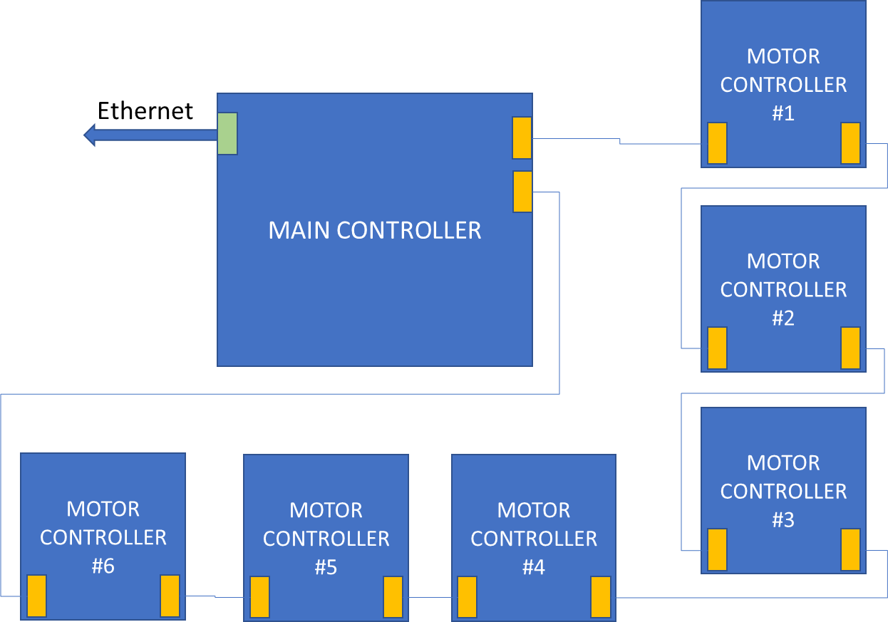
From the main controller, a high-speed communication bus transfers information to the satellite controllers. As in figure 2 we connect these controllers in a daisy chain configuration. Lastly, in physical terms, the motor control boards arrangement represents a ring.
Moreover, the main controller manages:
- automatic identification of the number of connected motor control boards
- automatic addressing of the motor control boards
- command and control data transfer to the motor control boards
- Motor’s: torque, flux, speed, position, start/stop
- Acquisition of the motor control boards variables
- All motor’s stator currents (3 currents)
- All motor’s stator voltages (3 voltages)
- Bus current and voltages (1 current 1 voltage)
- Hall sensors status as safety redundant motor’s position measurement for safety
- Absolute Encoder angle (position)
- Motor’s electrical speed
- Motor’s mechanical speed
- Acquisition of Functional Safety information
- Diagnostic status
- Integrity test
- Heartbeat signal transferred periodically
ROBOT'S POWER SUPPLIERS
The power supply shall provide 180W to the biopsy automation robot allowing a maximum of 24 motors @7A RMS. In addition it is highly recommended for systems that are operating in Class II to keep the DC bus at 12V or less as well as the motors in a delta configuration. Moreover, all power supplies will be generated by the main power system connected with double isolation to the main grid. Finally, the power supply shall operate from 110VAC to 240VAC.
CONCLUSION
To conclude, we have seen the main idea of how to build an automated assisting biopsy robot. Meanwhile, in the next article, we will talk about the motor control board. Stay tuned!

[…] You can find the first article here. […]
[…] you can find the first article here. Secondly, you can find the second article […]
[…] you can find the first article here. Secondly, you can find the second article here. Thirdly, you can find the third article […]