
Biopsy automation PT3: the motor control
INTRODUCTION
This is the third article of a series. which aim is a feasibility study for a modular system for biopsy. This system is composed of the main control board based on Xilinx ZYNQ Ultrascale+ and servo satellite motor drives based on Xilinx ZYNQ-7000. Accordingly, the objective of the system is to control a robot composed of multiple joints.
So, the biopsy is executed by driving one mechanical positioner composed of 6 Permanent Magnet Synchronous Motors (PMSM) motors and multiple joints, that are coordinated to position the biopsy needle on the desired target area.
Firstly, you can find the first article here.
Secondly, you can find the second article here.
MOTOR CONTROL BOARD
Bandwidth
Motor control requires synchronization to keep the system within a bandwidth of 1Khz. Therefore, the mechanism uses isochronous transfers as a time base for real-time transfers.
In particular, isochronous transfers have those properties:
- have a guaranteed bandwidth of 90 percent
- a sporadic data minimum of 10 percent
- the maximum data transferable per 1 millisecond is 6250 bytes
- every line has 24 devices
- sporadic traffic has 64 bytes
Clearly fewer devices allow more data payload.
Fault Tolerance
A fault may happen in one board, in the cable, or in the power supply that powers one motor control board. So, the system can reconfigure itself to detect the condition; accordingly, the system can:
- Execute a safe stop
- Execute a reconfiguration to work into degraded mode until a safe state is entered.
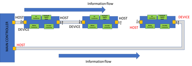
Figure 10 - Communication in degraded mode
The motor control board reconfigures the traffic into two segments to bring the system into a controllable condition where the application requires coordinated action to bring the system into a safe state. In Figure 10 the reconfiguration shows a broken element (motor control board, cable, power, motor, etc.). Thereafter, the new configuration of the communication flows with two host channels from the host to the device. The device to host follows the reconfiguration and the system works in a logical ring. The host sends the frame to the device, passed to the next one if existing, and the last device returns back using the full duplex capability of the frame to the host.
FOC
We are going to use a vector control technique called Field Oriented Control (FOC) in our motor control design. Then, the basic idea of the FOC algorithm is to decompose a stator current into a magnetic field-generating part and a torque-generating part and control them separately to achieve the best operating point. The motor is then an electrical to a mechanical transformer.
Accordingly, the motor control requires infrastructure elements to make the basic motor variables available, like currents, voltages, and shaft angle to the control algorithm. The PWM generates 6 PWM three-phase signals and drives a power bridge. Then, the Analog-Digital converter acquires the motor’s two stator currents, the voltages, and the DC_Link voltage. The Absolute Encoder Decoder provides the angle signal of the rotating motor shaft for closing the control loop. A set of hall sensors (3) supplements the encoder to have redundant low-precision feedback.
So, the FOC uses this infrastructure and controls the motor via a Space Vector Modulation (SVM).
All the Motor Control blocks are:
- Clark and Park Transform/Inverse Transform
- PID
- Trigonometric functions
- Sin/Cos
- Atan2
- Polar to Cartesian converter
- Cartesian to Polar converter
- IIR 2nd order filter with adjustable cut-off frequency for data acquisition
- Power Modulator for SVM (Space Vector Modulator)
- Encoder readout
FOC in application
FOC requires the following steps:
- Measure the motor quantities, phase voltages, and currents
- Transform them into the two-phase system using a Clarke transformation
- Calculate the rotor flux space-vector magnitude and position angle
- Transform stator currents into the d, q reference frame using a Park transformation. The position of the rotor determines the components.
- The stator current generates the torque (Isq) and flux (Isd) components.
- The output stator voltage space vector is calculated using a decoupling block
- The stator voltage space vector is transformed by an inverse Park transformation back from the d, q reference frame into the two-phase system fixed with the stator
- Space Vector Modulation generates three-phase voltages.
General Concept
The motor windings shown in Figure 11 top left, are offset 120 degrees from each other (a, b, and c). Thereafter, the PWM applies a stator voltage to the motor. The time integration of the stator voltage generates 3 almost sinusoidal currents (figure 11 bottom center). Then, the 3 phase currents generate a rotating electromotive vector Fs that spins the rotor.
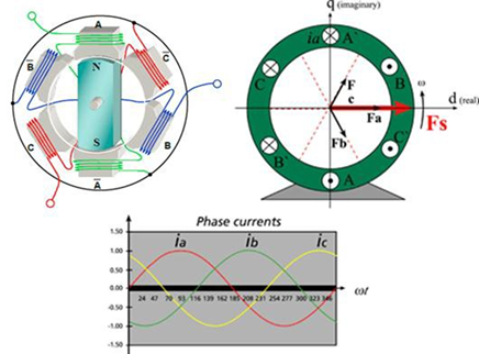
Figure 11 - PMSM concept description
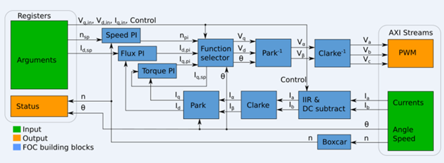
Figure 12 - FOC High-level block diagram
Conclusion
In this article, we saw how the FOC works. In the next article, we will talk about Clark and Park transformation. Stay tuned!

[…] Firstly, you can find the first article here. Secondly, you can find the second article here. Thirdly, you can find the third article here. […]