Biopsy automation PT2: boards communication
Main Characteristics
This is the second article of a series, which aim is a feasibility study for a modular system composed of the main control board based on Xilinx ZYNQ Ultrascale+ and servo satellite motor drives based on Xilinx ZYNQ-7000. The objective of the system is to control a robot composed of multiple joints. The article’s target is an automation of a prostate biopsy to assist doctors during medical procedures. The biopsy is executed by driving one mechanical positioner composed of 6 Permanent Magnet Synchronous Motors (PMSM) motors and multiple joints which coordinate the position of the biopsy needle on the desired target area. This second article will focus on the boards communication for synchronizing the motor controllers.
You can find the first article here.
MOTOR CONTROL BOARD
First, the motor control board implements the communication protocol, the safety functions, and the control loop.
Secondly, the estimated size of the motor control board is 40mm x 80mm including the power and communication connectors. Thirdly, the estimated size is budgetary and may be larger as the full mechanical and motor specifications will be consolidated.
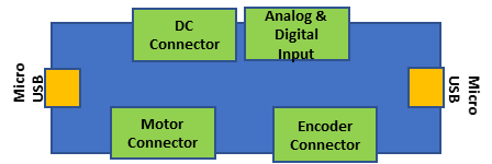
Figure 3 – Motor Control Board Outline
NON-SAFETY BLOCK DIAGRAM
The board's functional blocks are:
- System On Chip ZYNQ7000 XC7010
- N.1 16 Mbyte of Flash to store the program and the FPGA bitstream
- N.6 Power Mosfets IRF7480MTRPBF
- N.3 Gate Units LM5105SD/NOPB
- N.4 Current sensors ACS711KEXL T-15AB-T
- N.3 Analog to Digital converters (ADC) ADS7947SRTER 12-bits 2Msamples/s
- Current readout for DC_Link implemented by the 7010 internal ADC, 12-bits 1Msamples/s
- Voltage readout for DC_Link implemented by the 7010 7010 internal ADC 12 bits 1Msample/s
- N.2 RS485 Transceivers @50Mbit THVD2450 with 70V fault protected and IEC ESD
- Encoder data
- Encoder clock
- N.4 RS485 Transceivers @50Mbit THVD2450 with 70V fault protected and IEC ESD
- Redundant communication on both Input Channel Receiver and Transmission full duplex
- Redundant communication on both Output Channel Receiver and Transmission full duplex
- Hall Sensors signal conditioning
- JTAG connector for debugging
- DC/DC converter to power the system from the Main DC supply voltage.
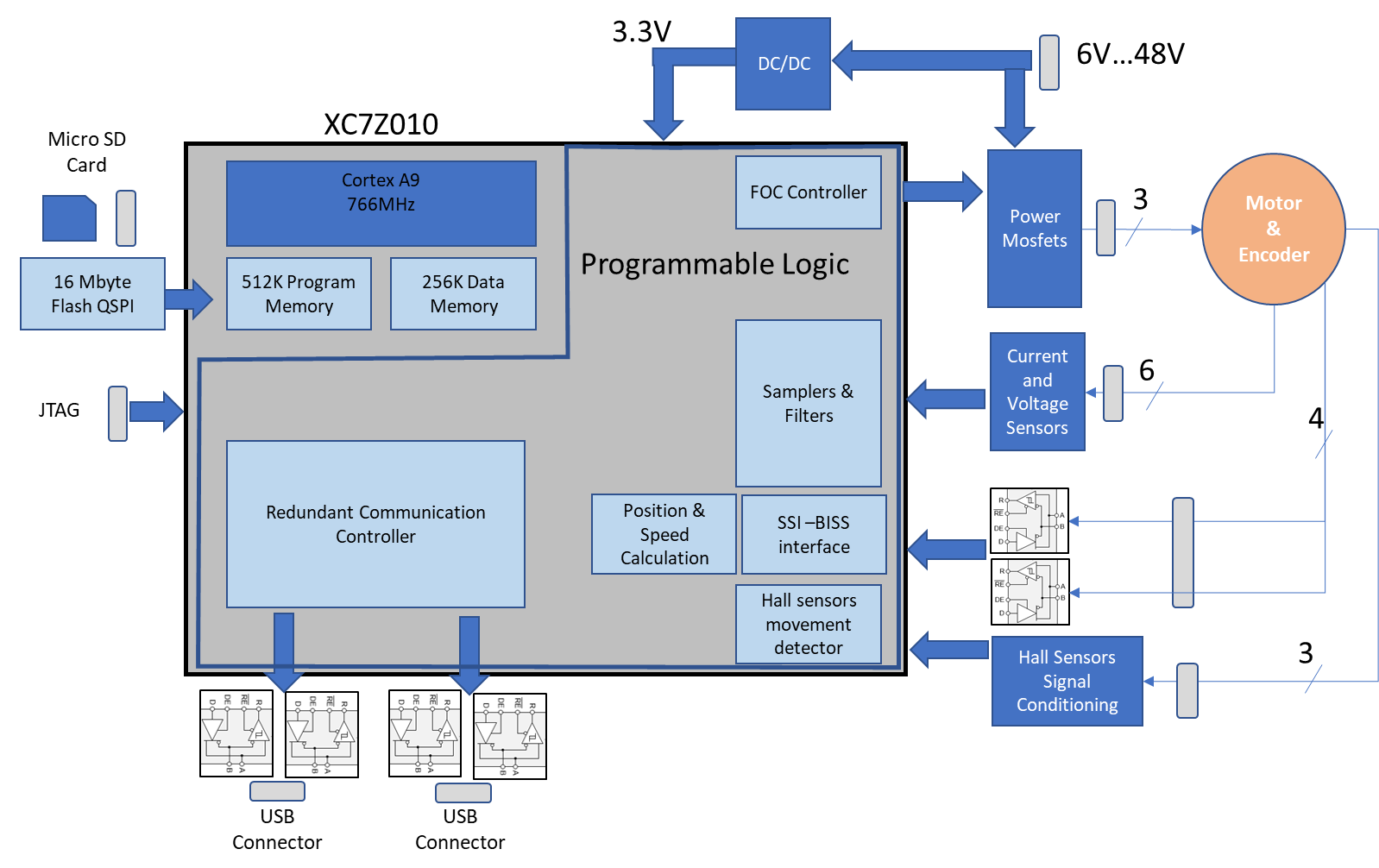
Figure 4 - Motor Control Board Block Diagram
REDUNDANT BOARDS COMMUNICATION
A micro-USB connector type with high retention is used to carry the communication bus signals. In particular, the USB connector does not implement the USB protocol, and its usage if being more cost-effective. The physical interface protocol is a RS485 with a datarate of 50Mbit/s. The RS485 uses the USB interface as a communication path. Moreover, the link layer uses a variant of the MVB protocol (IEC61375 Standard), and the physical layer encoding is Manchester or Bi-phase-L encoding.
"1" and "0" are bits that encode a cell as follows:
To obtain a "1" logic we need to have a HIGH level during the first half of a bit cell and a LOW for the second half.
To obtain a "0" logic we need to have a LOW level during the first half of a bit cell and a HIGH for the second half.
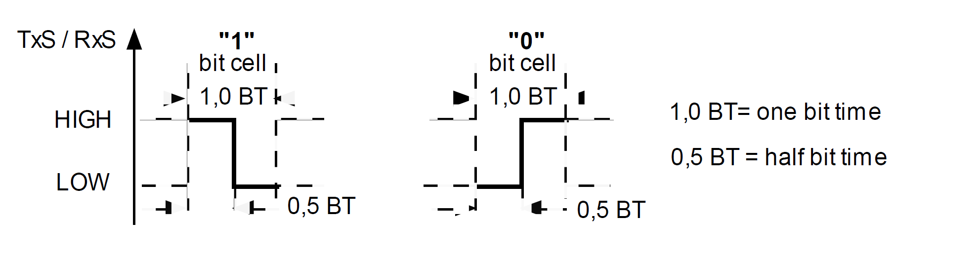
Figure 5 - Physical Layer Data Symbols
Non-Data symbols, NH and NL, are encoded in a bit cell as follows:
The communication has also Non-Data symbols, namely NH and NL. Specifically, the description of the symbols is:
So, to get a "NH" symbol we need to have HIGH level during a one-bit cell, whereas to get a "NL" symbol we need to have LOW level during a one-bit cell.
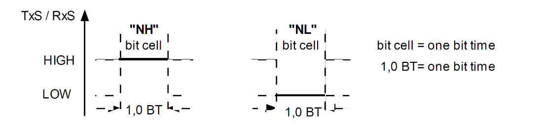
Figure 6 - Physical Layer Non-Data Symbols
To conclude this chapter, the advantage of such coding is the self-clocking capability that does not require asynchronous sampling.
Isochronous boards communication Transfer
Firstly, the division of the traffic consists of two different phases, a periodic and a sporadic phase. The rate of the frames is 1 ms.
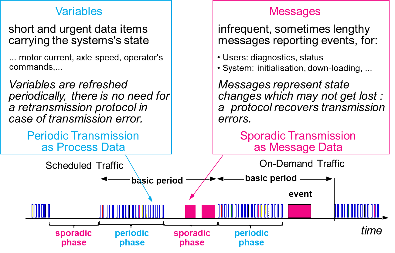
Figure 7 - Protocol Structure
Secondly, the ratio between the periodic phase and the sporadic phase is configurable depending on the traffic conditions.
The transmitter begins a frame with a Start Bit, sent as a "1" symbol.
The Start Delimiter of the frame consists of the sequence:
{Start Bit, "NH", "NL", "0", "NH, "NL", "0", "0", "0”}
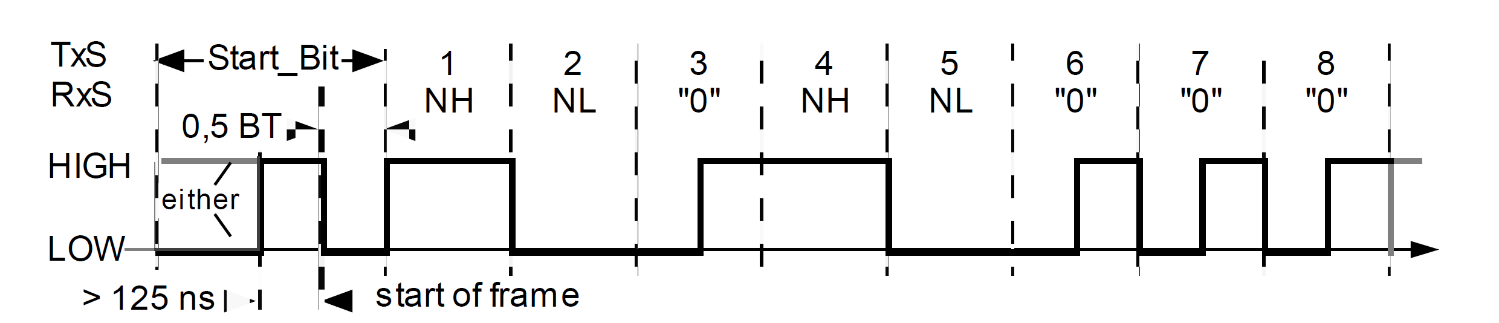
Figure 8 - Start Delimiter
The End Delimiter “NL” will cease the transmission.
Furthermore, each frame consists of a Start Delimiter (SD), and F_Code that informs the receiver about the data semantic, the Data Field, a CRC for data integrity followed by the End Delimiter (ED) that protects only the data field.
In particular, the Data Field contains additional information to identify to who the data belongs. In particular, the device number, the transactions counter, and the size of the data field.

The device in the chain receives the frame, adds its Data Field payload, and relays the frame into its output, forming a longer frame. For every device in the chain, we repeat the process.
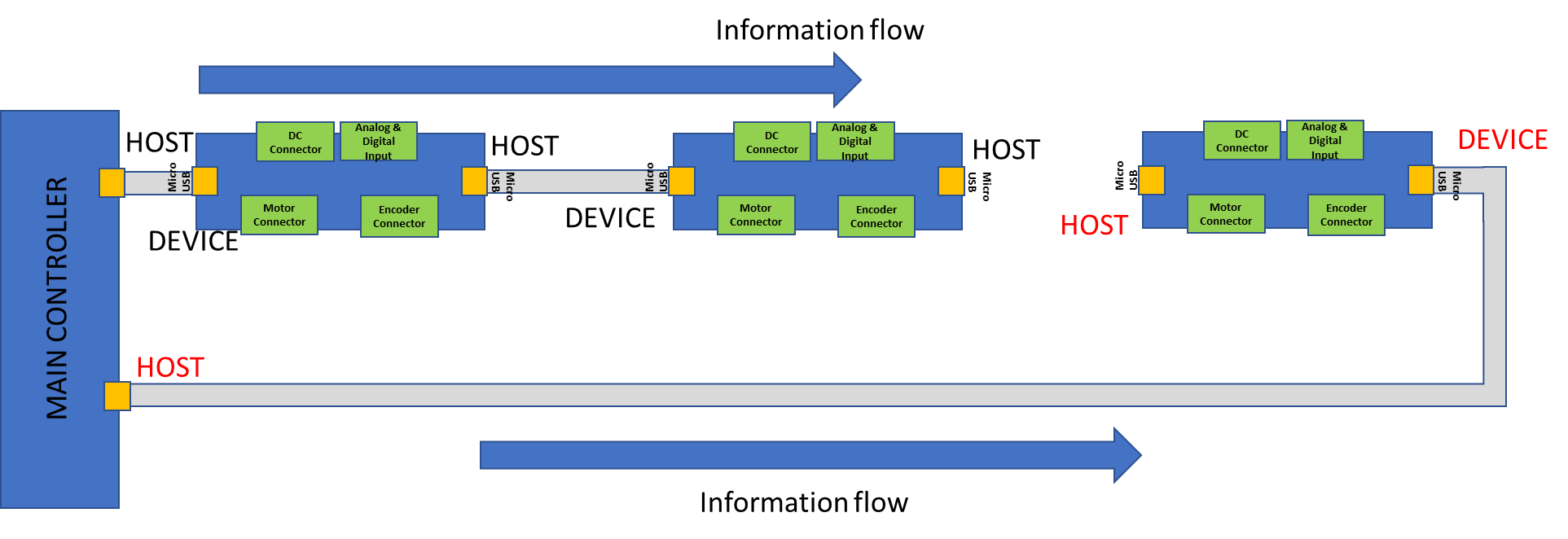
Figure 9
The last device in addition to relaying the compounded frame to its output changes the F_Code and relays the compounded frame to its input transmitter such that all the preceding devices receive the compounded data.
Lastly, within the basic period, all devices received the information of all devices.
Conclusion
This article broke down the communication between the motors. In the next one, we will talk about the FOC. Stay tuned!

[…] you can find the first article here. Secondly, you can find the second article here. Thirdly, you can find the third article […]
Thx!
[…] Firstly, you can find the first article here. Secondly, you can find the second article here. […]