
Biopsy Automation PT4: Motor Control – Clark and Park transformations
INTRODUCTION
This is the fourth article of a series, which aim is a feasibility study for a modular system for biopsy. In this article, we will focus on the common transformations for motor control: Clark and Park. This system is composed of the main control board based on Xilinx ZYNQ Ultrascale+ and servo satellite motor drives based on Xilinx ZYNQ-7000. Accordingly, the objective of the system is to control a robot composed of multiple joints.
So, you can execute the biopsy by driving one mechanical positioner composed of 6 PMSM motors and multiple joints. Those are coordinated to position the biopsy needle on the desired target area.
Firstly, you can find the first article here.
Secondly, you can find the second article here.
Thirdly, you can find the third article here.
MOTOR CONTROL BOARD: Clark and Park transformations
The FOC consists of controlling the components of the motor stator currents, represented by a vector, in a rotating reference frame d, q aligned with the rotor flux. The vector control system requires the dynamic model equations of the motor and returns the instantaneous currents and voltages in order to calculate and control the variables.
We describe the electric torque of a PMSM motor by the interaction between the rotor currents and the flux wave resulting from the stator currents. Since you cannot measure the rotor currents, we replaced this current with an equivalent quantity described in a rotating system coordinates called d,q following the rotor flux.
The Clarke transform uses three-phase currents a, b, and c to convert currents in the two-phase orthogonal stator axis: i-alpha and i-beta.
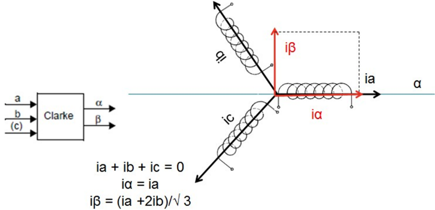
Clarke transformation (simplified)
Figure 13 - Clarke transformation (simplified)
These two currents in the fixed coordinates stator phase are transformed to the ISD and ISQ currents components in the [d,q] rotating frame with the Park transform using the electrical rotor’s angle as supplied by the Absolute Encoder SSI-BISS module.
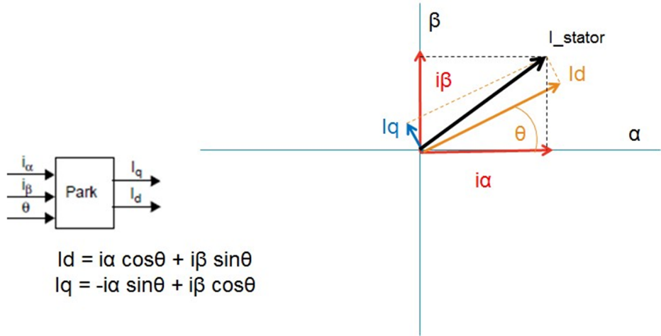
Figure 14 - Park's transformation (simplified)
Three Proportional Integral controller blocks regulate the difference between the desired torque, and flux to maintain the motor into the 90 magnetic/electric relationship.
The inverse Park’s transform is then used after the PID control to revert the Id, Iq values into Vα and Vβ stator voltages feeding the PWM Space Vector Modulator.
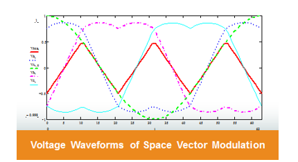
Figure 15 - Zero sequence injection space vector modulation
The SVM modulator produces a “pudding-shaped” waveform that instant by instant creates a homopolar structure, that adds and produces on the motor currents a sinusoidal flow.
Figure 16 shows the standard sinusoidal modulation that can use a maximum of 86% of the DC_Link (yellow zone) and the SVM allows up to 100% (red zone) before entering in non-linear motor movement (six steps).
Thus SVM allows better motor efficiency.

Figure 16 - Hexagon of the motor loci, yellow sinusoidal modulation, red SVM
The power stage is shown in Figure 17 where the Gate Drivers, the Mosfets, the current sensors, and the ADCs are all configured for the 3-phase system.
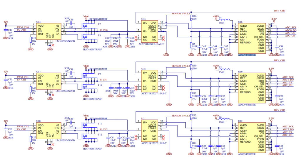
Figure 17- Full power stage with currents measurement
There are two basic configurations of three-phase motors, DELTA and WYE. An understanding of these two types of power may be important for the safe operation of three-phase equipment.
WYE Three-Phase
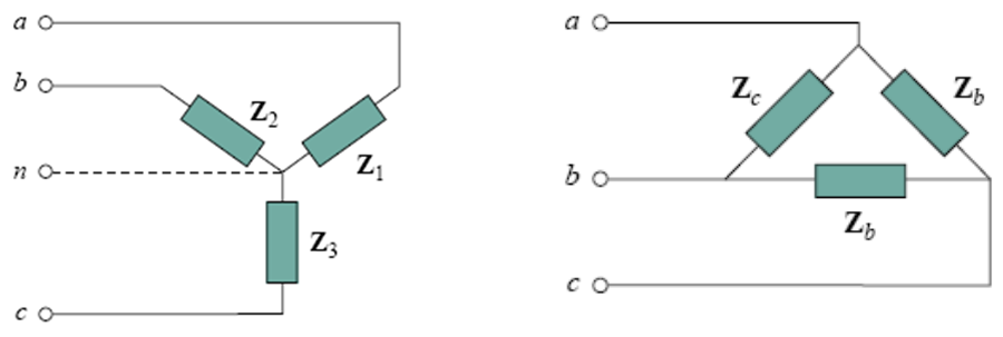
Figure 18 - Motor Connection Configurations WYE ( left ) DELTA (right)
Normally the community prefers DELTA connections when the total available voltage is small. DELTA are most common in medical applications. WYE connections are most common in industrial applications. For this application, we can use both configurations.
ABSOLUTE ENCODER WITH SSI INTERFACE FOR TRANSFORMATIONS
Usually, the engineering community uses Synchronous Serial Interface (SSI) as a standard serial interface for industrial applications especially, rotary encoders. It is a point-to-point connection from a master to a slave. In this type of interface, the sensor continually updates the position data and makes it available to the output register. The algorithm shifts the data when the sensor receives a pulse train from the controller. When the system transmits the least significant bit (LSB), the sensor holds the data constant for a certain time.
When this time has elapsed, the encoder continuously updated new position data in the output register. The Clock (CLK) and Data (DTA) signals are transmitted according to RS-422 standards that are compatible with the RS485 chips used in this design. The electrical characteristics of a differential voltage-driven transmission circuit. The advantage of differential signaling is the improved resistance to electromagnetic interference (EMI), especially in industrial environments and on more significant signal line (Transmission) lengths.
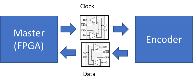
Figure 19 - SSI electrical interface
SSI Data is transferred in a single data word with the most significant bit (MSB) first. Encoders normally use 13 bits of data for transmitting the angle within one revolution (single turn). The system allows multi-turns as well.
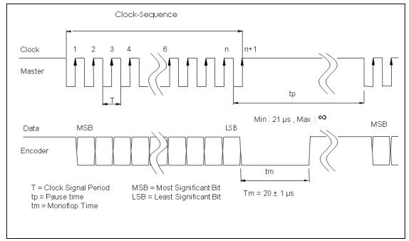
Figure 20 - SSI protocol
In Figure 20 the time ‘Tm’ represents the transfer timeout. The encoder requires the described time to recognize that a transfer is complete. The ‘tp’ label describes the pause time or the time delay between two consecutive clock sequences. It should always be greater than 21 µs; we cannot define the maximum time.
In an idle state, the encoder data line stays HIGH. After the first falling edge of the clock, the position value of the encoder remains constant, and the Data Level still remains in a HIGH state. With the first rising edge, the encoder transmits the first bit (MSB) at each rising clock edge. This will trigger the transmission of a bit. Finally, when the encoder transfers the LSB (end of transmission) an additional rising clock will set the data output to a LOW level. This signal remains low for 20 ±1 µs. After that, the encoder will start to update the position value continuously and set the data line to a HIGH state. The next transmission restarts with a train of clock pulses.
The maximum clock frequency can be to 2MHz or higher (period of 500ns). The minimum clock frequency is 50 KHz. The timeout definition determines this value. For example, a timeout time of 20 ±1 µs corresponds to 50 KHz.
Most SSI devices implement multiple transmissions. Multiple transmission, also known as ring shift or double transmission, can improve transfer safety by repeatedly reading the same data word.
The encoder will not update the data word before SSI timeout occurs. If the encoder continuously triggers the clock, it leads to multiple transmissions of the same position data without updating. The system can compare the data words inside the SSI Master to recognize transmission errors normally two transmissions are enough to ensure safe transmission.
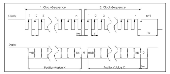
Figure 21 - ring shift transmission
Failure modes:
- The encoder does not respond with the Tm 20us +/- 1us LOW state followed by a LOW to HIGH transition. The system deems the encoder not operational
- In three-ring shift transmissions, at least two of the received data sets do not match. The system declares a protocol error, and the system flags safety demand.
- Torque is applied to the motor and hall sensors detect movements but the encoder does not update its position. Yhe system considers the encoder electrically good, but mechanically faulty.
Conclusion
In this article, we talked about the Clark and Park transformations. In the next and last article, we will talk about safety aspects and safety block diagrams. Stay tuned!