PacMan on KR260: RTL approach for retrogaming
Introduction
Are you tired of your beloved Pacman arcade cabinet collecting dust in the corner? Its components are outdated and impossible to find replacements? Fear not! With the power of FPGA technology and the AMD KR260, you can bring that classic game back to life and play it like it's 1980 all over again.
How do you port a retro gaming system like Pacman onto an FPGA? First, you gotta understand the hardware. That means breaking down the original cabinet's components and figuring out how to recreate them in code. And that's where RTL (Register-Transfer Level) comes in. It's a way of describing digital circuits in terms of registers, logic gates, and data paths. Sounds complicated, right? Well, it is, but it's also a lot of fun.
Once you've got your hardware description all figured out, it's time to fire up Vivado, the FPGA development environment. This is where you'll do all your coding, simulation, and testing. It's like a digital lab where you can experiment with different designs and configurations until you get everything just right.
And then, voila! You've got yourself a Pacman arcade machine running on FPGA technology. No more worrying about broken joysticks or faulty power supplies. Just pure, unadulterated retro gaming goodness.
So what are you waiting for? Dust off that old arcade cabinet and let's get porting!
Hardware description of Pacman cabinet
The Pacman arcade cabinet's motherboard is the central component of the machine and houses various critical components, including a Z80 CPU, which served as the heart of the system. The CPU was responsible for controlling the game's logic, graphics, and sound. Along with the CPU, the motherboard also had a VRAM (Video Random Access Memory), which stored the game's graphical data and allowed for smooth graphics rendering.
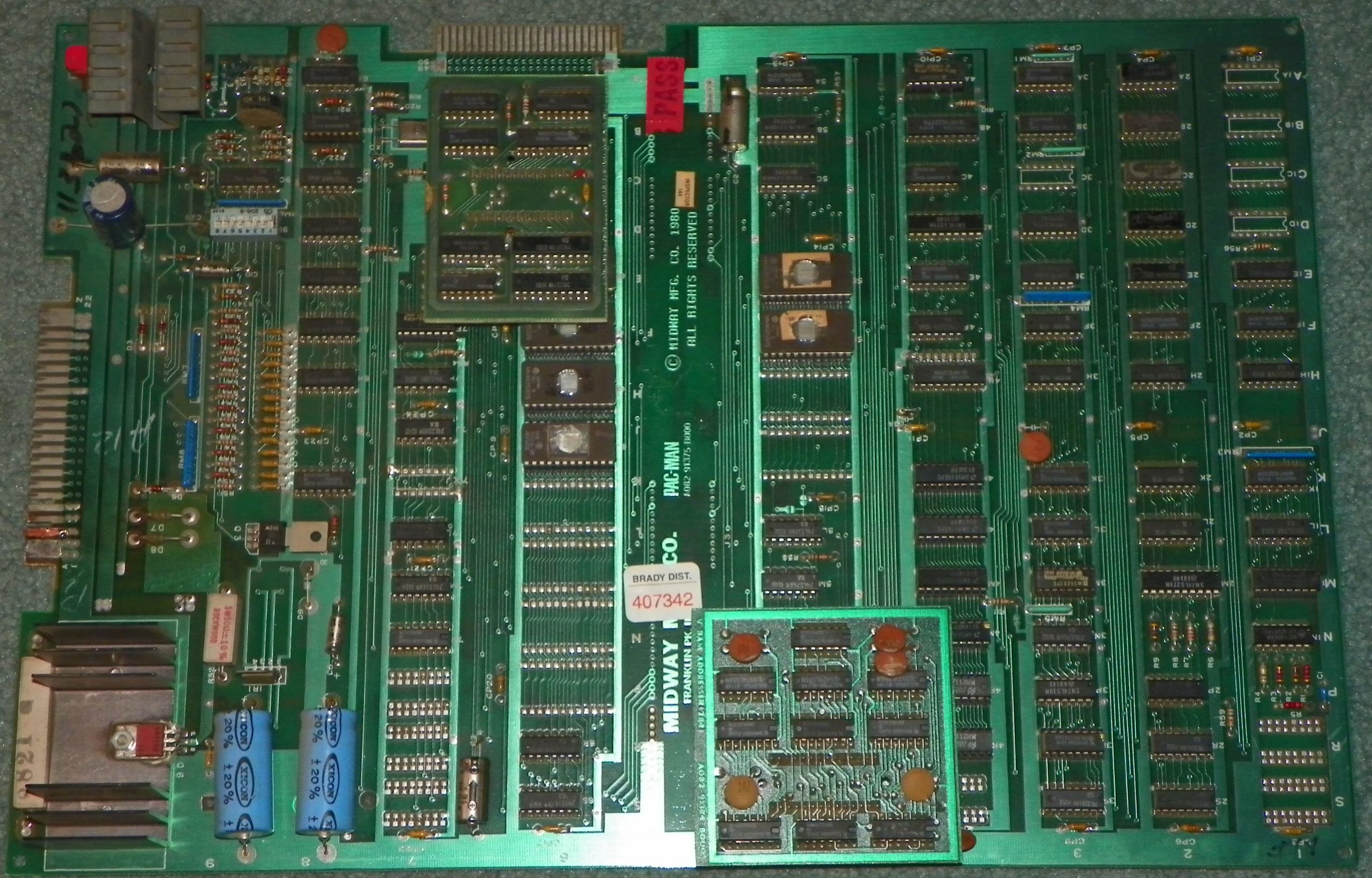
the Pacman motherboard (without cartridge)
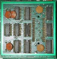
The V-RAM component
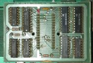
the Z-80 CPU component
The motherboard also contained several passive components, such as capacitors and resistors, which were essential for regulating the power supply and ensuring the stable operation of the system.
To load games onto the arcade machine, players could insert cartridges into a socket on the motherboard's side. Changing games was as simple as swapping cartridges (and maybe some soldering for custom cartridges). This system made it easy for arcade owners to offer new games to their customers without having to replace the entire machine. Overall, the Pacman arcade cabinet's motherboard was a robust and reliable piece of hardware that helped make the game an instant classic.
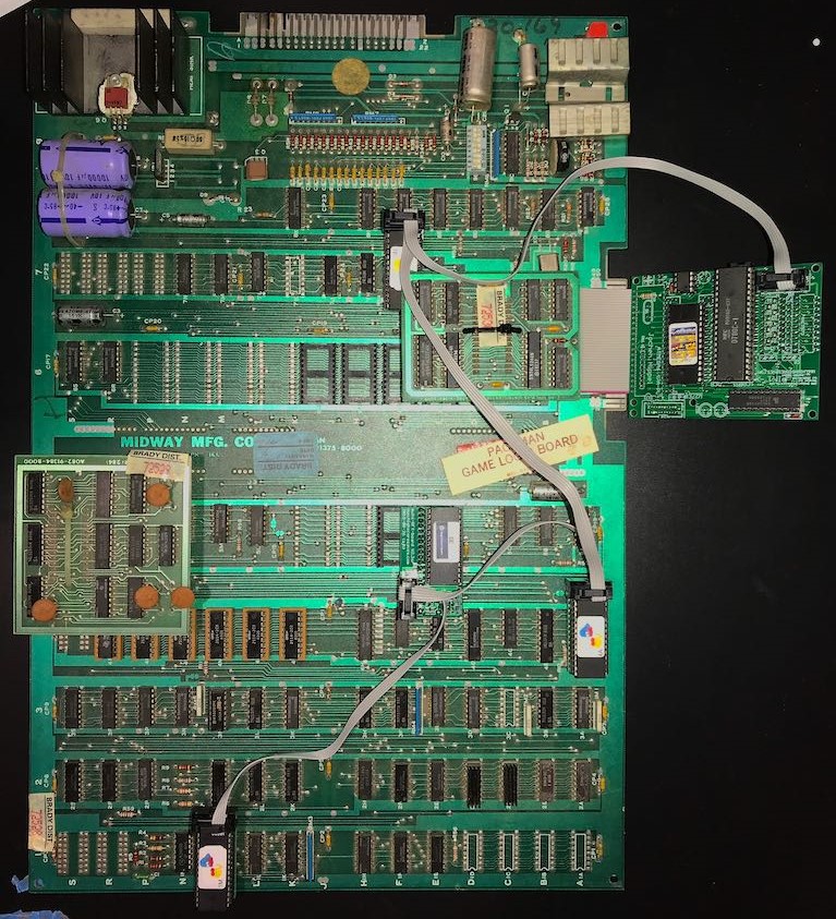
A motherboard with a custom cartridge of Pacman
The porting process of Pacman
The process of porting the components of Pacman's original motherboard into VHDL and Verilog involved reverse-engineering the original hardware and writing new code that emulated the functionality of each component. The first step was to analyze the behavior of each component and identify its essential features. Next, designers wrote new code that replicated these features in VHDL, using the same interfaces and functionality as the original hardware.
This process was repeated for each component of the Pacman arcade cabinet's motherboard, including the CPU and memory blocks. The end result was a complete VHDL implementation of the arcade machine's motherboard that could run on FPGA technology. This allowed retro gaming enthusiasts to enjoy the classic Pacman gameplay experience without worrying about the reliability of obsolete hardware components.
Fortunately, thank the GitHub community, Opencores community, and FPGAArcade by MikeJ we are able to find them all!
The main Pacman structure

The Pacman hardware design structure
The hardware design project includes an input system consisting of an array of inputs for the joystick and other inputs from the arcade cabinet. The other internal components will process these inputs.
The system also includes a clock generator that generates the necessary clock signals for the various components within the system. The clock generator converts the initial clock signal from the main board into multiple clock signals required for each component. This ensures that each component operates at the correct frequency and timing.
The CPU is the central component of the system and is responsible for executing the game logic. The VRAM provides a high-speed memory interface for storing and accessing the game graphics. The video timing component ensures that the VGA monitor will display correctly the video output.
The audio output is generated by the DAC, which converts the digital audio signals from the CPU into analog audio signals that the arcade machine's speakers will play it. The ROM reader and internal memory provide the storage space for the game code and data, while the input debouncer removes any false inputs from the joystick and other inputs.
Together, these components form a complete hardware system that emulates the original Pacman arcade machine's functionality. The input system captures user input, while the CPU processes game logic and the VRAM handles the game graphics.
Implementing Pacman on Vivado
Ok, so we have all for the system design! For convenience, all the source code is in the main repository of this project.
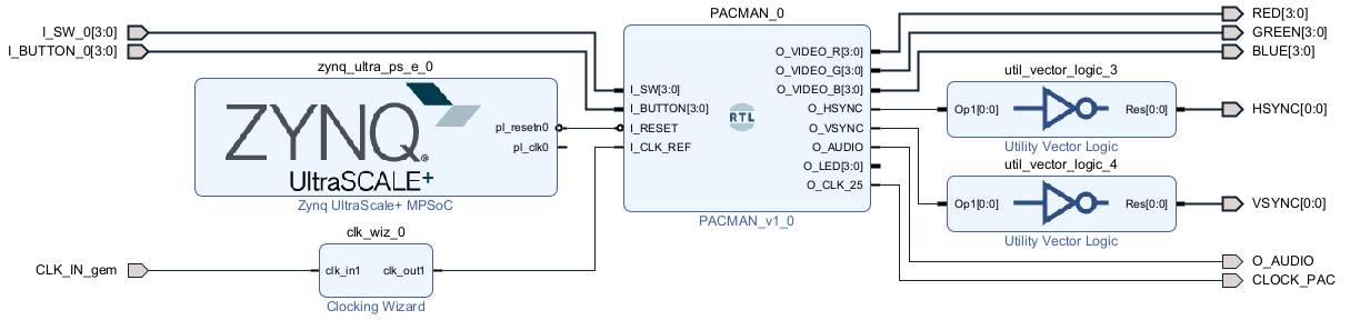
The Vivado design of Pacman
We can structure the Vivado design as follows:
- Main module - The main module (PACMAN_v1) from "pacman.vhd" file. This module contains the entire structure of the Pacman cabinet, including the CPU, VRAM, video output, audio output, and input debouncer.
- PS control - This module generates the reset signal for design initialization.
- Clocking - The board provides a clock signal from the oscillator of the KR260 carrier card, identified by the input CLK_IN_gem. Since this clock signal is at 25MHz, we need to brought up to 200MHz to operate the Pacman game correctly, so we have used a Clocking Wizard.
- Inputs - The Pacman game has two types of inputs - cabin inputs and joystick inputs. the I_SW inputs identify the cabinet inputs for controlling the game status, while the I_BUTTON inputs identify the joystick inputs and correspond to movements up, down, right, and left. The input debouncer ensures that the inputs received are valid and not erroneous.
- Outputs - The outputs of the design are the video output, the audio output, and a debug output. The video output consists of three 12-bit color values (RGB). Also, HSYNC and VSYNC signals will synchronize the VGA display. Finally, we have used a debug output (CLOCK_PAC) to verify that the generated clock is at 25MHz and that the game is running correctly.
Start the Game!
Now we have all! Let's compile the bitstream and load it to the KR260.
But, before that, we need to configure the hardware properly. For the Switches part, we can use some simple cables to the 3.3v, meanwhile, for the joystick, we can use some buttons connected in pull-up configuration.
For VGA output, you can use a PMOD VGA adapter. We have used this one by Digilent. Connect the PMOD VGA to the PMOD 3-4. The command buttons are mapped in PMOD 1 [5-6-7-8] and the Switch pins are mapped in PMOD 1 [1-2-3-4].
Before loading the bitstream, make sure that pin 4 of PMOD 1 is set to +3.3V to activate VGA in PAL double scanline compatible mode.
So, Connect the KR260 to your computer via USB. To enable the KR260 to upload the bitstream, run the following commands via XSCT:
- connect
- targets -set -nocase -filter {name =~ "*PSU*"}
- mwr 0xff5e0200 0x0100
- rst -system
Finally, on Vivado, click on PROGRAM AND DEBUG -> Program Device and...
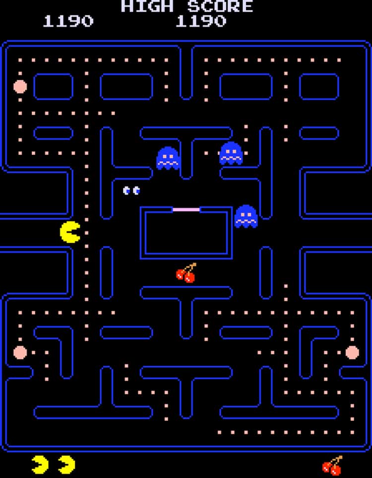
pacman screenshot
Voilà! You can play Pacman on your board!
Change the Pacman cabinet ROM
Unfortunately, we cannot share directly the Pacman ROM on our GitHub because an official license is needed. But we have provided you a simple utility to transform an original or compatible ROM dump to your design!
First, you need to download a MAME ROM (for example this one). If you notice, there are a lot of files in the downloaded zip file:
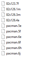
Those files correspond to the ROM memory sectors that we need to translate into VHDL for our design.
Let's take a look at our repository in the "rom-generator" directory. We have provided a bat file (build_roms_pacman.bat) that allows you to compile all the files for your design.
So, if you want to load a different ROM, you must modify the tcl file (project/design_1.tcl) at line 27 with the new ROM directory. If you change this file, you need to recreate the entire project (remove the project/pacman_kr260 directory and re-launch "source design_1.tcl").
- PacMan (Midway)
- Dream Shopper
- Eggor
- Gorkans
- Lizard Wizard
- Mr. TNT
- Ms. Pacman
- Pacman Club
- Pacman Plus
- Ponpoko
- Puck Man (original Japan PacMan)
- Woodpecker

[…] PacMan on KR260: RTL approach for retrogaming […]