Microblaze on PYNQ: soft processor on FPGA
Introduction
FPGA programming is not only based on a hardware design, you also can also create software that runs on different soft processors on it, called “MicroBlaze”. This kind of design is useful in specific applications, such as protocol implementation, system orchestration, and soft-realtime systems.
The aim of this article is to reproduce a little architecture that supports this soft processor, controlling a simple peripheral such as a GPIO, using the PYNQ framework for instantiation and controlling.
What is a MicroBlaze
The MicroBlaze IP describes a soft microprocessor, that is a microprocessor core completely implemented using logic synthesis. Using this kind of microprocessor, you can write a little software using C or C++ code that runs on your Xilinx FPGA. Obviously, you can instantiate on your design a lot of MicroBlaze, so you can parallelize your system with different software (FPGA size permitted).
MicroBlaze IP is represented on Vivado in this way:
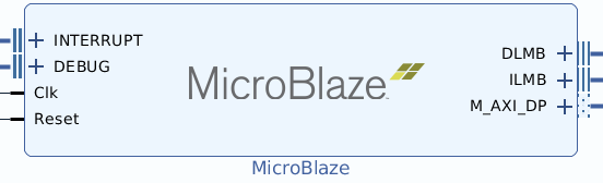
As you can see, the MicroBlaze design has an M-Axi port for peripheral communication (through an Axi Interconnect), an Interrupt port for asynchronous activation, a Debug port for debugging the code, and 2 memory ports for the local memory (that is a BRAM memory).
So, let’s start to design a complete system!
Vivado design for MicroBlaze
Due to the fact that MicroBlaze is a “real” microprocessor and it can run compiled software, you need to connect it to memory for 2 main reasons:
- every microprocessor needs memory for loading the program (for text, stack, and heap section)
- the only method that you have for communicating with the microprocessor is shared memory, like common IPC strategies
In fact, if you see in the MicroBlaze design, there is no “slave port” that connect the Processing system and the MicroBlaze, but the Processing system can write on a BRAM as a slave! So, we will use a BRAM memory for the MicroBlaze communication (as a shared memory strategy)
Processing system
The processing system section of the design (PS) is the same as every Vivado design. If you need more details, please see our other articles:
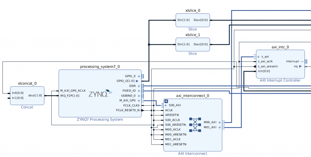
As usual, you need to instantiate a Processing System, an Axi interconnect that connects the PS to the Axi interrupt controller and the Microblaze hierarchy (we will describe it in the next section). Then, you need to enable the GPIO EMIO of the PS, which will manage the start of the Microblaze execution. Finally, you need to enable the PS interrupts.
In general, for every Microblaze you need 2 PS GPIOs: one for the interrupt controller reset pin on the Microblaze and one for the Microblaze reset pin; PYNQ drivers will manage them without your intervention.
The PS part of Vivado design will be the following:
The Microblaze Hierarchy
Due the fact that the MicroBlaze design is a little bit complex, we need to create a Vivado hierarchy. When the hierarchy design will be complete, you can copy and paste in your Vivado design for simple multiple instantiations.
The hierarchy is composed by:
- MicroBlaze
- Axi BRAM Controller
- Processor system Reset
- Local Memory
- Axi interconnect (for Microblaze – Peripheral connection)
- an Axi Interrupt Controller
- Axi GPIO for interrupt control
- Reset Vector (that you can inherit from the PYNQ repository)
First, you need to upgrade your IP repository with the PYNQ IP repository; you can set it through:
Settings -> IP -> Repository
and add {PYNQ repository directory}/boards/ip
Then, connect the IPs in this way:
- Axi interconnect of the PS to the Axi BRAM Controller
- First PS GPIO to aux_reset_in of the Processor System Reset
- all the clocks together
- 0 constant to intr pin of Axi Interrupt Controller
- 1 constant to ext_reset_in of the Processor System Reset
- M_AXI_DP output of Microblaze to slave input of Axi Interconnect
- M00_AXI output of Axi Interconnect to Axi Interrupt Controller
- Reset Vector output to the intr input of PS Axi Interrupt Controller
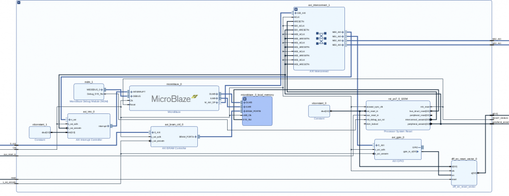
It is a little complicate design, right? Don’t worry, at the end of the tutorial we will share the entire code.
The design is the following:
Memory settings
Now is important to set the memory addressing, in order to set the memory size of the BRAM and the addressing of Microblaze. In this case, Vivado is your friend: it will automate the placing using the “Assign all” command (right-click on the unassigned address and select “assign all”). Then, you need to set the range of BRAM IPs to 64K (in order to have 16K of memory).
If everything is right, you have this configuration:
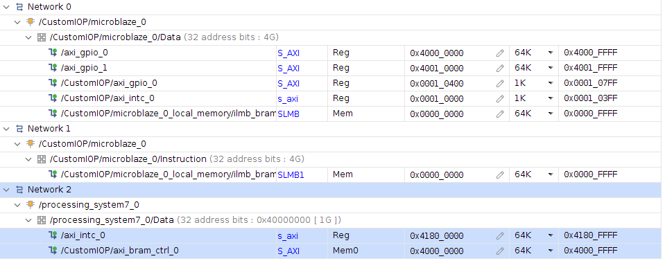
Notice some things:
- there are 3 networks, one for the IPs, one for the instruction addressing of Microblaze, one for the data addressing of Microblaze
- the BRAM IP address in Network 0 is different from the BRAM data address in Network 2, this is because the addressing maybe have different visibility on PS
At the end, you have a similar design like that:
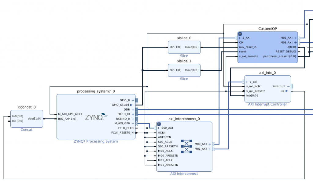
Notice that the hierarchy (in this case called “Custom IOP”) is collapsed.
After that, you can connect every peripheral you need in your design through the Axi interconnect internal to the hierarchy.
Finally, generate the bitstream as usual and export the XSA file.
Microblaze software
Now, how can I generate the code that will run on the Microblaze? With another software: Vitis IDE.

Vitis IDE can be run through the Vivado Tools menu. You just need to create a new Application project, selecting in the platform menu the XSA file and create a blank C project.
In this application, we will control a GPIO, turning on and off the output (for example, you can attach to the pin of your board a led).
The code is the following:
/***************************** Include Files *********************************/
#include "xparameters.h"
#include "xgpio.h"
#include "xil_printf.h"
#include "circular_buffer.h"
/************************** Constant Definitions *****************************/
#define LED 0x01   /* Assumes bit 0 of GPIO is connected to an LED  */
/*
* The following constants map to the XPAR parameters created in the
* xparameters.h file. They are defined here such that a user can easily
* change all the needed parameters in one place.
*/
#define GPIO_EXAMPLE_DEVICE_ID  XPAR_GPIO_1_DEVICE_ID
/*
* The following constant is used to wait after an LED is turned on to make
* sure that it is visible to the human eye.  This constant might need to be
* tuned for faster or slower processor speeds.
*/
#define LED_DELAY     10000000/2
/*
* The following constant is used to determine which channel of the GPIO is
* used for the LED if there are 2 channels supported.
*/
#define LED_CHANNEL 1
#define WRITE_LED	0x9
#define READ_LED 	0x23
#define TEST_CYCLE 	0x69
/**************************** Type Definitions *******************************/
/***************** Macros (Inline Functions) Definitions *********************/
#ifdef PRE_2_00A_APPLICATION
/*
* The following macros are provided to allow an application to compile that
* uses an older version of the driver (pre 2.00a) which did not have a channel
* parameter. Note that the channel parameter is fixed as channel 1.
*/
#define XGpio_SetDataDirection(InstancePtr, DirectionMask) \
XGpio_SetDataDirection(InstancePtr, LED_CHANNEL, DirectionMask)
#define XGpio_DiscreteRead(InstancePtr) \
XGpio_DiscreteRead(InstancePtr, LED_CHANNEL)
#define XGpio_DiscreteWrite(InstancePtr, Mask) \
XGpio_DiscreteWrite(InstancePtr, LED_CHANNEL, Mask)
#define XGpio_DiscreteSet(InstancePtr, Mask) \
XGpio_DiscreteSet(InstancePtr, LED_CHANNEL, Mask)
#endif
/************************** Function Prototypes ******************************/
/************************** Variable Definitions *****************************/
/*
* The following are declared globally so they are zeroed and so they are
* easily accessible from a debugger
*/
XGpio Gpio; /* The Instance of the GPIO Driver */
/*****************************************************************************/
/**
*
* The purpose of this function is to illustrate how to use the GPIO
* driver to turn on and off an LED.
*
*
* @return	XST_FAILURE to indicate that the GPIO Initialization had
*		failed.
*
* @note		This function will not return if the test is running.
*
******************************************************************************/
int main(void)
{
int Status;
volatile int Delay;
int led_status = 0;
int cmd;
u16 data;
/* Initialize the GPIO driver */
Status = XGpio_Initialize(&Gpio, GPIO_EXAMPLE_DEVICE_ID);
if (Status != XST_SUCCESS) {
xil_printf("Gpio Initialization Failed\r\n");
return XST_FAILURE;
}
/* Set the direction for all signals as inputs except the LED output */
XGpio_SetDataDirection(&Gpio, LED_CHANNEL, ~LED);
while (1) {
// waiting a command from PS
while((MAILBOX_CMD_ADDR & 0x01)==0);
cmd = MAILBOX_CMD_ADDR;
switch(cmd){
case WRITE_LED:
data = (u16) MAILBOX_DATA(0);
if(data == 1){
/* Set the LED to High */
XGpio_DiscreteWrite(&Gpio, LED_CHANNEL, LED);
} else {
XGpio_DiscreteClear(&Gpio, LED_CHANNEL, LED);
}
led_status = data;
MAILBOX_CMD_ADDR = 0x0;
break;
case READ_LED:
MAILBOX_DATA(0) = (u16) led_status;
MAILBOX_CMD_ADDR = 0x0;
break;
case TEST_CYCLE:
MAILBOX_CMD_ADDR = 0x0;
for(int j = 0; j < 1000000; ++j){
XGpio_DiscreteWrite(&Gpio, LED_CHANNEL, LED);
for (Delay = 0; Delay < LED_DELAY; Delay++);
XGpio_DiscreteClear(&Gpio, LED_CHANNEL, LED);
}
break;
default:
MAILBOX_CMD_ADDR = 0x0;
break;
}
}
}
Notice that the XGpio function is generated by the Vitis platform (the XSA file). You communicate with the PS with the MAILBOX macro, which is an address in the BRAM memory that is visible from the PS (like a shared memory).
The Mailbox is defined in the circular_buffer.h file:
#ifndef _CIRCULAR_BUFFER_H_
#define _CIRCULAR_BUFFER_H_
#ifdef __cplusplus
extern "C" {
#endif
#include
#include "xil_types.h"
#define MAILBOX_CMD_ADDR       (*(volatile u32 *)(0x0000FFFC))
#define MAILBOX_DATA(x)        (*(volatile u32 *)(0x0000F000 +((x)*4)))
#define MAILBOX_DATA_PTR(x)    ( (volatile u32 *)(0x0000F000 +((x)*4)))
#define MAILBOX_DATA_FLOAT(x)     (*(volatile float *)(0x0000F000 +((x)*4)))
#define MAILBOX_DATA_FLOAT_PTR(x) ( (volatile float *)(0x0000F000 +((x)*4)))
#ifdef __cplusplus
}
#endif
#endif  // _CIRCULAR_BUFFER_H_
We need to use the same addressing in the PYNQ code.
So, just compile it and, if you have no errors, modify a little the makefile (because we need the bin file, not the elf file).
-include ../makefile.init
RM := rm -rf
# All of the sources participating in the build are defined here
-include sources.mk
-include src/subdir.mk
-include subdir.mk
-include objects.mk
ifneq ($(MAKECMDGOALS),clean)
ifneq ($(strip $(S_UPPER_DEPS)),)
-include $(S_UPPER_DEPS)
endif
ifneq ($(strip $(C_DEPS)),)
-include $(C_DEPS)
endif
endif
-include ../makefile.defs
# Add inputs and outputs from these tool invocations to the build variables
ELFSIZE += \
main.elf.size \
# All Target
all: main.elf secondary-outputs
# Tool invocations
main.elf: $(OBJS) ../src/lscript.ld $(USER_OBJS)
@echo 'Building target: $@'
@echo 'Invoking: MicroBlaze gcc linker'
mb-gcc -Wl,-T -Wl,../src/lscript.ld -L/home/pynq/workspace_vitis_ide/microblaze/export/microblaze/sw/microblaze/standalone_domain/bsplib/lib -mlittle-endian -mcpu=v11.0 -mxl-soft-mul -Wl,--no-relax -Wl,--gc-sections -o "main.elf" $(OBJS) $(USER_OBJS) $(LIBS)
@echo 'Finished building target: $@'
@echo ' '
main.elf.size: main.elf
@echo 'Invoking: MicroBlaze Print Size'
mb-size main.elf  |tee "main.elf.size"
@echo 'Finished building: $@'
@echo ' '
# ADD THIS!
main.bin: main.elf
@echo 'Invoking: MicroBlaze Bin Gen'
mb-objcopy -O binary main.elf main.bin
@echo 'Finished building: $@'
@echo ' '
# Other Targets
clean:
-$(RM) $(EXECUTABLES)$(OBJS)$(S_UPPER_DEPS)$(C_DEPS)$(ELFSIZE) main.elf
-@echo ' '
# ADD THIS!
secondary-outputs: $(ELFSIZE) main.bin
.PHONY: all clean dependents
-include ../makefile.targets
Then, go to the Debug or Release directory of your project and run make clean && make. You now will obtain the bin file!
PYNQ Code
Finally, we are ready to deploy both the bitstream file from Vivado and the binary executable from Vitis IDE.
The PYNQ framework, as usual, make available some cool stuff regarding the IPs control. In the PYNQ library is present the class PynqMicroblaze, which allows you to instantiate and communicate with the Microblaze.
The PynqMicroblaze need a descriptor of the design, in order to give to the bitstream the right signals and start your application; so you need to define a dictionary in this way:
descriptor = {
'ip_name': < full path of BRAM controller >,
'rst_name': < slice IP name that manage the reset pin >,
'intr_pin_name': < dff_en_reset_vector path >,
'intr_ack_name': < slice IP name that manage the interrupt reset pin >
}
So, in our case according to the design, we can define the descriptor in this way:
customIOP = {
'ip_name': 'CustomIOP/axi_bram_ctrl_0',
'rst_name': "xlslice_0",
'intr_pin_name': "CustomIOP/dff_en_reset_vector_0/q",
'intr_ack_name': "xlslice_1"
}
Next, we need to define the same addresses and command that we have choose on the firmware code
# mailbox address offset
MAILBOX_OFFSET = 0xF000
MAILBOX_SIZE = 0x1000
MAILBOX_PY2IOP_CMD_OFFSET = 0xffc
MAILBOX_PY2IOP_ADDR_OFFSET = 0xff8
MAILBOX_PY2IOP_DATA_OFFSET = 0xf00
# commands
WRITE_LED = 0x9
READ_LED = 0x23
TEST_CYCLE = 0X69
Finally, we can define the python program, that does the following:
- define the PynqMicroblaze custom class
- load the bitstream
- load the binary program to the Microblaze
- send and receive commands and data through Mailbox
A slice of cake 🙂
from pynq import Overlay
from pynq.lib import PynqMicroblaze
class MB(PynqMicroblaze):
def __init__(self, mb_info, mb_program):
super().__init__(mb_info, mb_program)
def write_mailbox(self, data_offset, data):
offset = MAILBOX_OFFSET + data_offset
self.write(offset, data)
def read_mailbox(self, data_offset, num_words=1):
offset = MAILBOX_OFFSET + data_offset
return self.read(offset, num_words)
def write_blocking_command(self, command):
self.write(MAILBOX_OFFSET + MAILBOX_PY2IOP_CMD_OFFSET, command)
while self.read(MAILBOX_OFFSET + MAILBOX_PY2IOP_CMD_OFFSET) != 0:
pass
def write_blocking_command_addr(self, addr, command):
self.write(addr, command)
while self.read(addr) != 0:
pass
def write_non_blocking_command(self, command):
self.write(MAILBOX_OFFSET + MAILBOX_PY2IOP_CMD_OFFSET, command)
ol = Overlay("design_1.bit")
mb_info = customIOP
_mb = MB(mb_info, "main.bin")
# turn on LED
_mb.write_mailbox(0, 1)
_mb.write_blocking_command(WRITE_LED)
# read LED state
_mb.write_mailbox(0, 0)
_mb.write_blocking_command(READ_LED)
And now the magic happens!
Conclusion
In this article we have seen how to create a complete design that use a soft processor in the FPGA.
You can find the project code here:
https://github.com/MakarenaLabs/PYNQ-Microblaze-Tutorial
Now you are ready to create a more complex design that uses this incredible feature on Xilinx FPGA with the PYNQ framework!

[…] So, here is the thing: using the Arduino as a bridge (like a USB Device), we can use it to communicate between a USB Host and an FPGA. In order to communicate with the Arduino, we will use the I2C protocol and a Microblaze for the device driver. Do you remember our article for I2C design on FPGA and Microblaze? […]
What Pynq board is the bit file synthesised for ?
Hi Tony! The bitstream is for the Pynq Z2 board, but you can recompile it for another board using the vivado ticle file as you wish 👍
Hi, thanks for the tutorial. I have a question regarding MicroBlaze reset from ARM. Is this necessary and if yes, can you please explain why? Thanks in advance 🙂
Hi! thanks 🙂
the reset signal is not mandatory (but very useful!), because if you restart the Jupyter Notebook or reload the MicroBlaze binary, you have to reset the MicroBlaze from the PS.
Hello! I have a question regarding the AXI BRAM controller. It seems when creating my block design, I cannot figure out how to get BRAM_PORTB to work from the local memory when I set it to external from inside the generated block IP. My address editor just says that it is unconnected and it cannot work. I am missing something, do you know what?
Hi! We noticed that sometimes Vivado cannot refresh all the hierarchy dependences, so, after assigning the addresses, try to regenerate the block design
I have a question about generating the bin file. It seems that whenever I edit the make file to include the bin file in outputs, when I go to build/compile from within Vitis IDE, it restores the make file to it’s default state. Is there a reason for this? I cannot get the bin file to output in the directory.
Hi! sorry for the delay…
Unfortunately this is a problem related to the toolchain, so try to ask directly to the Xilinx forum. Usually, a little workaround is to copy all the files in a different directory and compile them on it.
Hello, I’m trying to replicate this tutorial in Vivado 2018. I’m unable to find where the files for the custom Ip are at. Please let me know the steps to replicate this design. Thanks!
Hello! The custom IPs are on the PYNQ repo.
In the tutorial, in the step “add {PYNQ repository directory}/boards/ip”, before that you need to download PYNQ from github, and then in your project you need to import the ips.
The IPs are the following:
https://github.com/Xilinx/PYNQ/tree/master/boards/ip
Hello and thanks for the tutorial.
I am using Vitis 2024.1.0 and cannot find how to modify the makefile to generate the MB “bin” file.
A simple makefile does not seem to be available with this version.
Could you help? thanks.
Hi, I am traversing your example with my Z2 board as I need to do similar for the Ultra96 and have encountered an inconsistancy in your block design that creates a problem for address mapping. After running the .tcl for vivado, both axi_gpios blocks in the design are named axi_gpio_0. The .pdf and you screenshots show them both as axi_gpio_0. Can you recall which one is supposed to be named axi_gpio_1? Thanks!
I got it working! Thank you very much for posting this! axi_gpio_1 in the memory map was probably some residue from your debugging or whatnot.
And… your customIOP descriptor in cell #3 of main.ipynb doesnt work. I copied the code snippet you have above for the descriptor and that worked. Well done!