FPGA as USB Device: universal communication with PYNQ
Introduction
One of the main problems of embedded systems is the external communication, in particular for the FPGAs: you need in every specific situation a different protocol and different strategies for inter-communication with a host system. That’s why the USB protocol is useful and, in particular, for a complex device such as the FPGA. In this article, we will define a simple but robust approach for designing an FPGA as a USB Device.
The USB system
Universal Serial Bus (USB) is an industry-standard that establishes specifications for cables, connectors, and protocols for connection, communication, and power supply (interfacing) between computers, peripherals, and other computers. So, is not only the common “cable” that we use to recharge our phone or the USB pen drive that contains all of our photos and documents, but it is a complete standard that includes hardware, middleware, and software.
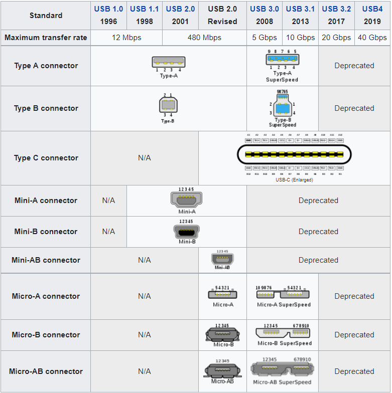
There are a lot of connectors available, that define the standard protocol version, the maximum transfer rate, and the robustness of the shell. Here there is a summary table:
In the protocol part, there are 3 types of actors:
- the host is the computer or item that acts as the main element or controller for the USB system
- the device is the peripheral with a specific role in the USB system, with an ID and a descriptor
- the hub is a device that expands the topology of the USB system
So, a USB network consists of a single host with one or more downstream ports, and multiple peripherals, forming a tiered-star topology.
The USB Device Classes
The most interesting idea behind the USB is the Device Classes of a USB device. A USB device defines its functionalities with a class code, that it sends to a host during the initial pairing. This allows the host to load software modules for the device and to support new devices from different manufacturers.
For example:
- 01h stands for Interface/Audio
- 03h stands for Interface/Human Interface Device (HID)
- 07h stands for printer
- etc.
So, thanks to the USB Device Classes, you can communicate with a USB Device just by using the device driver of your PC without analyzing tons of documentation or implementing a thousand lines of code.
That’s why the USB interface is self-configuring, eliminating the need for the user to adjust the device’s settings for speed or data format or configure interrupts, input/output addresses, or direct memory access channels. It’s a universal language (and that’s why often your printer goes crazy 😜 ).
Why FPGA as USB Device
Imagine that you need to delegate a lot of computational tasks to a peripheral from your PC, it is very difficult (and not cheap) to send your data through UART protocol to an FPGA. Or imagine that you need to respect hard real-time constraints in your system and you need to send a lot of data; you can’t use a standard 802.11.X topology. Or, simply, you need an easy way to communicate with your FPGA for task monitoring or “health monitoring” of your system.
In every case, a USB protocol is a viable and elegant solution for the design of your system.
The only problem here is that the FPGA needs a physical transceiver in order to implement and use the USB protocol, and also the USB Device IP core on Vivado is not completely free to use.
So, why don’t we use a MacGyver solution?

The architecture
Every embedded geek knows a little device that supports USB by design: the Arduino board.
The Arduino board is composed of an ATMega328 for the microcontroller part and an ATMega16u2 for the USB communication part. This second component is not very known because it is hidden in the Arduino toolchain.
Thanks to NicoHood Github user, it is available a new bootloader that enables you to use also the 16u2 MCU on the Arduino board. This new bootloader is called HoodLoader2 and, after following the hardware installation and software installation, you are ready to use the MCU that is the best candidate for the USB communication (is born for that purpose).
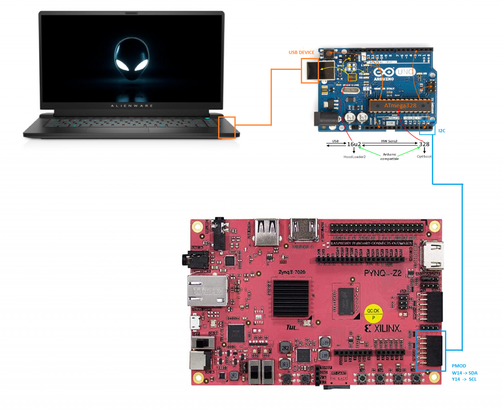
So, here is the thing: using the Arduino as a bridge (like a USB Device), we can use it to communicate between a USB Host and an FPGA. In order to communicate with the Arduino, we will use the I2C protocol and a Microblaze for the device driver. Do you remember our article for I2C design on FPGA and Microblaze?
For this project, we decide to use the PYNQ Z2 board.
Vivado Design
The Vivado design is quite easy: we need to use the standard Microblaze design compatible with PYNQ system and we need to attach the I2C to the Microblaze AXI. We decide to use Microblaze in order to implement the entire design on PL side. Using Microblaze, you will get also the device driver directly when you will use the Vitis IDE tool during the design of the software.
Remember that you need to connect the interrupt pin of the I2C to the Interrupt input of the Microblaze, in order to enable the API feature (for example, the “busy bus” interrupt and the “communication finished” interrupt).
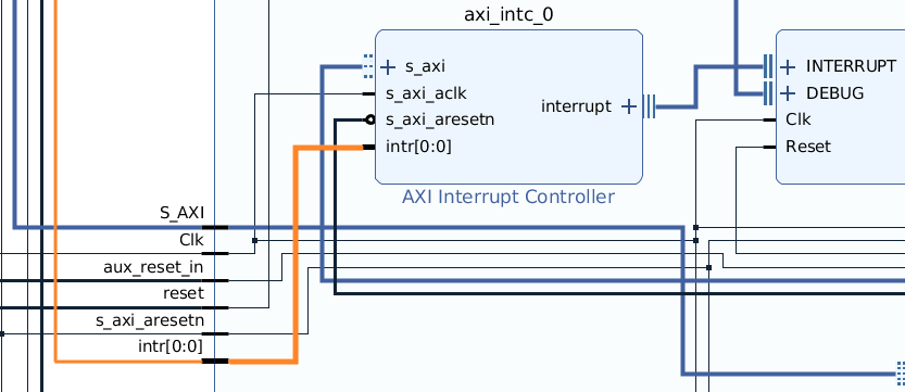
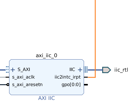
So, the design will look like that:
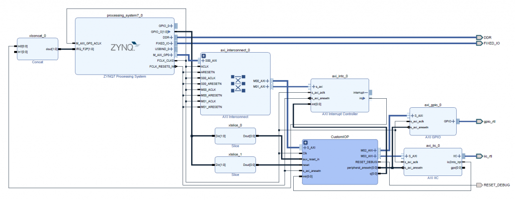
Notice the connection between the AXI interrupt of the Microblaze subsystem and the I2C interrupt, this is necessary for the I2C APIs in the Microblaze!
Vitis IDE
After the generation of the bitstream, you need to define the code that will run on the Microblaze. So, open Vitis IDE, create the platform from the generated XSA, and use the I2C APIs.
In particular, you need to communicate with the PYNQ framework through the Mailbox style (that is like a shared memory as we said in the Microblaze article) and, with a defined command, you will send a specific character to the slave. In this particular case, you will send a single character, but you can extend it to an arbitrary length.
So, the code will look like that:
#include "xparameters.h"
#include "xil_types.h"
#include "xiic.h"
#include "xintc.h"
#define MAILBOX_CMD_ADDR       (*(volatile u32 *)(0x0000FFFC))
#define MAILBOX_DATA(x)        (*(volatile u32 *)(0x0000F000 +((x)*4)))
#define MAILBOX_DATA_PTR(x)    ( (volatile u32 *)(0x0000F000 +((x)*4)))
#define MAILBOX_DATA_FLOAT(x)     (*(volatile float *)(0x0000F000 +((x)*4)))
#define MAILBOX_DATA_FLOAT_PTR(x) ( (volatile float *)(0x0000F000 +((x)*4)))
#define TEST 	0x69
#define SEND	0x9
#define INIT 	0x23
#define IIC_DEVICE_ID		XPAR_IIC_0_DEVICE_ID
#define INTC_DEVICE_ID		XPAR_INTC_0_DEVICE_ID
#define IIC_INTR_ID			XPAR_INTC_0_IIC_0_VEC_ID
/*
* The following constant defines the address of the IIC
* device on the IIC bus. Note that since
* the address is only 7 bits, this  constant is the address divided by 2.
*/
#define ARDUINO_ADDRESS	0x4 /* The actual address is 0x4 */
#define SEND_COUNT	16
#define RECEIVE_COUNT   16
XIic Iic;		  /* The instance of the IIC device */
XIic_Config *ConfigPtr;
XIntc InterruptController;
u8 WriteBuffer[SEND_COUNT];	/* Write buffer for writing a page. */
u8 ReadBuffer[RECEIVE_COUNT];	/* Read buffer for reading a page. */
volatile u8 TransmitComplete;
volatile u8 ReceiveComplete;
static int SetupInterruptSystem(XIic *IicInstPtr)
{
int Status;
if (InterruptController.IsStarted == XIL_COMPONENT_IS_STARTED) {
return XST_SUCCESS;
}
/*
* Initialize the interrupt controller driver so that it's ready to use.
*/
Status = XIntc_Initialize(&InterruptController, INTC_DEVICE_ID);
if (Status != XST_SUCCESS) {
return XST_FAILURE;
}
/*
* Connect the device driver handler that will be called when an
* interrupt for the device occurs, the handler defined above performs
*  the specific interrupt processing for the device.
*/
Status = XIntc_Connect(&InterruptController, IIC_INTR_ID,
(XInterruptHandler) XIic_InterruptHandler,
IicInstPtr);
if (Status != XST_SUCCESS) {
return XST_FAILURE;
}
/*
* Start the interrupt controller so interrupts are enabled for all
* devices that cause interrupts.
*/
Status = XIntc_Start(&InterruptController, XIN_REAL_MODE);
if (Status != XST_SUCCESS) {
return XST_FAILURE;
}
/*
* Enable the interrupts for the IIC device.
*/
XIntc_Enable(&InterruptController, IIC_INTR_ID);
/*
* Initialize the exception table.
*/
Xil_ExceptionInit();
/*
* Register the interrupt controller handler with the exception table.
*/
Xil_ExceptionRegisterHandler(XIL_EXCEPTION_ID_INT,
(Xil_ExceptionHandler) XIntc_InterruptHandler,
&InterruptController);
/*
* Enable non-critical exceptions.
*/
Xil_ExceptionEnable();
return XST_SUCCESS;
}
static void SendHandler(XIic *InstancePtr)
{
TransmitComplete = 0;
}
static void ReceiveHandler(XIic *InstancePtr)
{
ReceiveComplete = 0;
}
static void StatusHandler(XIic *InstancePtr, int Event)
{
}
int IicInit(u16 IicDeviceId, u8 ArduinoAddress){
int Status;
/*
* Initialize the IIC driver so that it is ready to use.
*/
ConfigPtr = XIic_LookupConfig(IicDeviceId);
if (ConfigPtr == NULL) {
return XST_FAILURE;
}
Status = XIic_CfgInitialize(&Iic, ConfigPtr,
ConfigPtr->BaseAddress);
if (Status != XST_SUCCESS) {
return XST_FAILURE;
}
Status = SetupInterruptSystem(&Iic);
if (Status != XST_SUCCESS) {
return XST_FAILURE;
}
/*
* Set the Transmit, Receive and Status handlers.
*/
XIic_SetSendHandler(&Iic, &Iic,
(XIic_Handler) SendHandler);
XIic_SetRecvHandler(&Iic, &Iic,
(XIic_Handler) ReceiveHandler);
XIic_SetStatusHandler(&Iic, &Iic,
(XIic_StatusHandler) StatusHandler);
Status = XIic_SetAddress(&Iic, XII_ADDR_TO_SEND_TYPE, ArduinoAddress);
if (Status != XST_SUCCESS) {
return XST_FAILURE;
}
return Status;
}
int SendArduinoIIC(u16 IicDeviceId, u8 ArduinoAddress, u8 *ArduinoPtr, u8* TxData, u16 TxLength)
{
int Status;
u8 Index;
for (Index = 0; Index < SEND_COUNT; Index++) {
WriteBuffer[Index] = 0;
ReadBuffer[Index] = 0;
}
TransmitComplete = 1;
Iic.Options = 0x0;
Status = XIic_Start(&Iic);
if (Status != XST_SUCCESS) {
return XST_FAILURE;
}
//	IicInstance.Options = XII_REPEATED_START_OPTION;
Status = XIic_MasterSend(&Iic, TxData, TxLength);
if (Status != XST_SUCCESS) {
return XST_FAILURE;
}
/*
* Wait till data is transmitted.
*/
while ((TransmitComplete) || (XIic_IsIicBusy(&Iic) == TRUE)) {
}
Status = XIic_Stop(&Iic);
if (Status != XST_SUCCESS) {
return XST_FAILURE;
}
return XST_SUCCESS;
}
int main(void)
{
int Status;
int cmd;
u8 data[16] = {0};
u8 data_len = 1;
u8 ArduinoPtr;
u8 ArduinoAddress = 0;
while (1) {
while((MAILBOX_CMD_ADDR & 0x01)==0);
cmd = MAILBOX_CMD_ADDR;
switch(cmd){
case TEST:
MAILBOX_DATA(0) = 69;
MAILBOX_CMD_ADDR = 0x0;
break;
case INIT:
ArduinoAddress = (u16) MAILBOX_DATA(0);
IicInit(IIC_DEVICE_ID, ArduinoAddress);
MAILBOX_CMD_ADDR = 0x0;
break;
case SEND:
data[0] = (u16) MAILBOX_DATA(0);
data_len = (u16) MAILBOX_DATA(1);
Status =  SendArduinoIIC(IIC_DEVICE_ID, ArduinoAddress, &ArduinoPtr, data, data_len);
MAILBOX_DATA(0) = (u16) Status;
MAILBOX_CMD_ADDR = 0x0;
break;
default:
MAILBOX_CMD_ADDR = 0x0;
break;
}
}
return 0;
}
Arduino Code
Now we need to work in the Arduino domain.
We decide to use the HID device class and in particular the Keyboard profile (just for the demo, in order to simplify the design). The algorithm is the following: when the Arduino receives the ‘W’ character, it will send to the USB Host the ‘w’ character. Due to the fact that is a common USB Device, we don’t need to install anything on the Host side, we will need only to plug the USB Device and receive the character!
Remember that, in this particular project, due to the fact that we use the I2C protocol, you need to define two different software: one for the 16U2, and one for the ATMega328. If you want to use UART or SPI, you can use only the 16U2 MCU.
So, the ATMega328 will receive the characters through I2C from the PYNQ board and will send them through the internal Serial bus to the MCU, and the MCU will interpret the character and send it to the USB Host.
This is the code of ATMega328P:
#include "Wire.h"
char buffer[100];
int incount=0;
int outcount=0;
int x=0;
#define MAX_CHAR 1
bool new_char = false;
void setup (void)
{
Serial.begin(115200);
Wire.begin(4);                // join i2c bus with address #4
Wire.onReceive(receiveEvent); // register event
}  // end of setup
void loop()
{
if(new_char){
new_char = false;
Serial.write(buffer[0]);
buffer[0] = 0;
}
}
// function that executes whenever data is received from master
// this function is registered as an event, see setup()
void receiveEvent(int howMany)
{
new_char = true;
buffer[0] = Wire.read();
}
On the MCU code we have used the BootKeyboard class, that initialize the Keyboard HID class and send the character to the USB Host. This is the MCU code:
#include "HID-Project.h"
#include "pins_arduino.h"
const int pinLed = LED_BUILTIN;
const int pinButton = 2;
#define UL unsigned long
#define US unsigned short
int ss_pin = PB7;
void SlaveInit(void) {
Serial1.begin(115200);
}
//WW
void setup() {
pinMode(pinLed, OUTPUT);
digitalWrite(pinLed, HIGH);
SlaveInit();  // set up SPI slave mode
delay(1000);
// Sends a clean report to the host. This is important on any Arduino type.
BootKeyboard.begin();
}
void loop() {
while (!Serial1.available()){;}
char c = Serial1.read();
if(c == 'W'){
digitalWrite(pinLed, LOW);
BootKeyboard.write(KEY_W);
delay(1000);
digitalWrite(pinLed, HIGH);
}
}
Notice that this is a very simple code because the Arduino itself is used as a bridge, so it don’t need any complex task to do.
Jupyter Notebook
Finally, let’s define the Jupyter Notebook for this project!
It is a very simple code (due to the fact that everything is done on the PL side, so the PS side is used as an initiator).
We need only to download the bitstream file, download the ELF file to the Microblaze and send the character through Mailbox.
This is the python code:
from pynq import Overlay
from pynq.lib import PynqMicroblaze
ol = Overlay("usb_microblaze.bit")
customIOP = {
'ip_name': ol.CustomIOP.description["memories"]["axi_bram_ctrl_0"]["fullpath"], #'CustomIOP/axi_bram_ctrl_0',
'rst_name': "xlslice_0", #'mb_iop_pmoda_reset',
'intr_pin_name': "CustomIOP/dff_en_reset_vector_0/q", #'iop_pmoda/dff_en_reset_vector_0/q'
'intr_ack_name': "xlslice_1"#'mb_iop_pmoda_intr_ack'
}
MAILBOX_OFFSET = 0xF000
MAILBOX_SIZE = 0x1000
MAILBOX_PY2IOP_CMD_OFFSET = 0xffc
MAILBOX_PY2IOP_ADDR_OFFSET = 0xff8
MAILBOX_PY2IOP_DATA_OFFSET = 0xf00
TEST = 0x69
SEND = 0x9
INIT = 0x23
ARDUINO_ADDRESS = 0x04
mb_info = customIOP
_mb = MB(mb_info, "usb_microblaze.bin")
_mb.write_mailbox(0, 0)
_mb.write_blocking_command(TEST)
_mb.read_mailbox(0x0)
_mb.write_mailbox(0, 4)
_mb.write_blocking_command(INIT)
_mb.read_mailbox(0x0)
for i in range(0,10):
time.sleep(1)
_mb.write_mailbox(0, 87) # 'W'
_mb.write_mailbox(4, 1)
_mb.write_blocking_command(SEND)
_mb.read_mailbox(0x0)
If everything is ok, you will see on your PC that your “virtual keyboard” writes the ‘w’ character on your Jupyter Notebook. It’s cool, right? 😎
Conclusions
This simple tutorial shows that you can create a simple design that configures an FPGA as a USB Device with an Arduino bridge.
You can find the full project here: https://github.com/MakarenaLabs/USB-Device-on-PYNQ-using-Arduino
That’s only scratching the surface of what you can do on the USB Device. Imagine that you need a simple and real-time way to communicate the inference result of a neural network on the FPGA to your PC, or you need to send a bulk data to the FPGA and you can’t use the Ethernet interface, these can be done with this simple but strong solution.
See you soon for the next tutorial!
Shared project, double project
It’s a good tutorial demonstrating MB and IIC in FPGA project, as well as cross platform integration. But giving the nature of IIC between FPGA and Arduino, it won’t be faster then a simple USB-UART dongle.