
PWM on PYNQ: how to control a stepper motor
Pulse width modulation (PWM) is a modulation technique that generates variable-width pulses to represent the amplitude of an analog input signal.
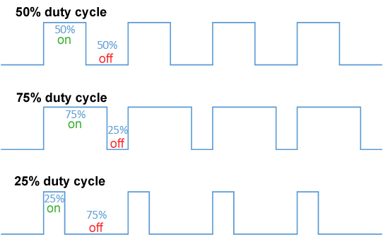
We are interested in two parameters: signal frequency (or period), and the signal duty cycle:
- The Period is the time that the signal takes to be low and high
- The duty cycle is the ratio of the high time to the period of the signal.
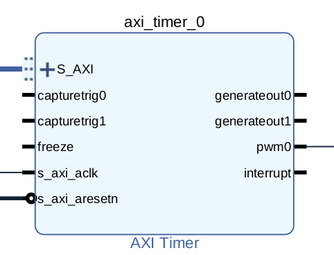
The only IP core that provides Xilinx that can generate a PWM signal is the Axi Timer. Axi Timer is controlled by a S_AXI interface and it get outs two kinds of outputs:
- a timer output, for generating a simple clock timer
- a PWM, for generating a PWM signal
So, according to that, we will create a design that generates a PWM signal connected to a specific PIN of the PYNQ Z2.
The Vivado flow is the usual flow:
- add the Zynq processing system
- place an Axi interconnect, with Master Axi as many as you need for connecting Axi Timer
- add some Axi Timer (as many as you need for PWM signals)
- create pinout interfaces with the right constraints according to the PMOD pinout, see this article if you need to know how)
- connect all together
For instance, this is a possible design for the purpose:
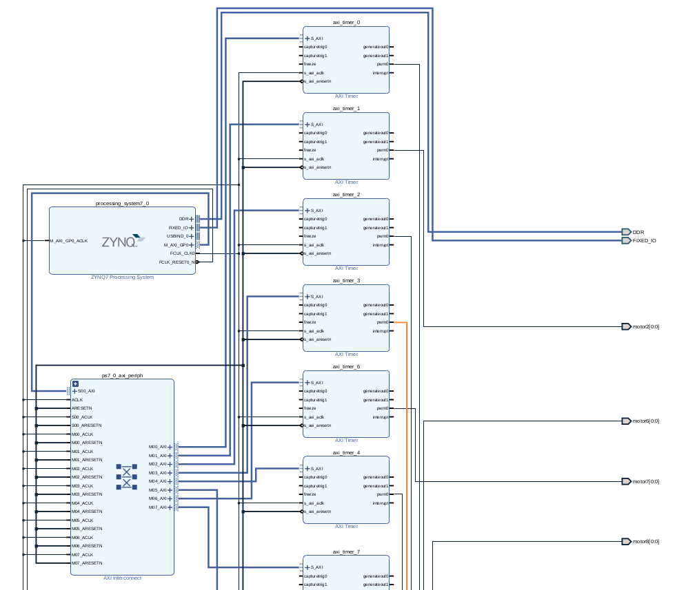
pretty cool, uhm?
In our design, we have defined this constraint file (we need 8 PWM signals, so we have connect all of the PMODB pins):
So, now we have the bitstream. How we can use it? You must read the documentation of the Axi Timer😋
The Axi Timer documentation is here: https://www.xilinx.com/support/documentation/ip_documentation/axi_timer/v2_0/pg079-axi-timer.pdf
As with every peripheral, you need to control the control/status register shown below:
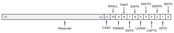 So, we need to write on the specific bits of this register the value in order to activate the PWM signal generator.
In particular, we need this configuration:
- The PWMA0 bit in TCSR0 and PWMB0 bit in TCSR1 must be set to 1 to enable PWM mode
- The GenerateOut signals must be enabled in the TCSR (bit GENT set to 1). The PWM0 signal is generated from the GenerateOut signals of Timer 0 and Timer 1, so these signals must be enabled in both timer/counters;
- The counter UDT can be set to count up or down (we prefer to set to 1);
- set Autoreload register ARHT0 to 1;
- enable timer setting ENT0 to 1.
After that, we can set the period and the duty cycle of the generated PWM signal.
Ok, now we are ready to control the PWM! Here is some PYNQ code for PWM generation (on single Axi Timer)

Great explanation!
even though it is not a great deal, do you mind changing the motor name to motor1 at the beginning?
It was quite helpful to understand how the timer works to generate PWM. I was using a simpler version if anyone is interested :). It served me well.
from pynq import Overlay
overlay = Overlay(“pwm.bit”)
motor1 = overlay.axi_timer_0
period = 10000 # 1 is highest frequency possible, generally decrease with increasing the value
duty_cycle = 60
motor1.register_map.TCSR0= int(motor1.register_map.TCSR0) | 646
motor1.register_map.TCSR1= int(motor1.register_map.TCSR1) | 646
motor1.register_map.TLR0= period
motor1.register_map.TLR1= (duty_cycle & 0x07f) * int(motor1.register_map.TLR0)/ 100;
Thank you for the report! we have changed the typo right now 🙂
EG
[…] Axi timer article […]
Hello, I saw in your conclusion that you would teach us how to control a Stepper motor with a PYNQ Z2 board. But I haven’t seen this article on your official website. May I ask when you will release it? I’m looking forward to it. Thank you for sharing!
Hi! Happy to know it from you 😊
We will release it in the next weeks!
Hello, what is your version of Vivada? Can you share the corresponding project directory of this article?
[…] Welcome to part 2 of the previous article about PWM signals and PYNQ! In this article, we will show what is a servo motor and how to control a servo motor with the previous design of the PWM on the PYNQ framework, with a simple “recipe”. If you have missed the previous article, you can find it here! […]
Hello, what is your version of Vivada? Can you share the corresponding project directory of this article?
Hello, the used version of Vivado is 2021.1, but it is compatible with every version of Vivado!
Unfortunately, we don’t have a project repository, but it is described the full flow and code in this article 😁 If you want to visit our Github, it is here: https://github.com/orgs/MakarenaLabs/repositories
谢谢你的回答,我在vivado2020运行,但是出现问题了,
TCSR0 = ol.ip_dict[‘axi_timer_0’][‘registers’][‘TCSR0’]
key error “registers”
Thank you for your answer. I run in Vivado2020, but there is a problem,
TCSR0 = ol.ip_ dict[‘axi_timer_0’][‘registers’][‘TCSR0’]
key error “registers”
if you print ol.ip_ dict[‘axi_timer_0’], what is the output?
Thank you for your answer. Sorry, I’m in the dormitory now, but pynq-z2 is in the laboratory. I will run the program tomorrow, but I remember print ol.ip_ Dict [‘axi_timer_0 ‘] is a dictionary that does not contain “registers”
Can I see your complete Vivado design for PWM picture?, I can’t guarantee that my connection line is correct
Hello, an error occurred while running this code
KeyError Traceback (most recent call last)
in ()
15 print(ol.ip_dict[‘axi_timer_0’])
16 # extract register addresses (will be the same for every Axi Timer)
—> 17 TCSR0 = ol.ip_ dict[‘axi_timer_0’][‘registers’][‘TCSR0’]
18 TCSR1 = ol.ip_ dict[‘axi_timer_0’][‘registers’][‘TCSR1’]
19 # TCSR0_ address = TCSR0[‘address_offset’]
KeyError: ‘registers’
—————————————————————————
print ol.ip_ dict[‘axi_timer_0’]
{‘fullpath’: ‘axi_timer_0’, ‘type’: ‘xilinx.com:ip:axi_timer:2.0’, ‘state’: None, ‘addr_range’: 65536, ‘phys_addr’: 1115684864, ‘gpio’: {}, ‘interrupts’: {}, ‘driver’: }
Ok, I think that you haven’t assigned any address to the axi. Follow these steps:
1. open block design
2. open the “Address Editor” tab
3. right click on the top-level network (in your project I think is “Network 0”)
4. click on “Assign all”
5. recompile all (generate bitstream)
Thank you for your answer, but there is still this error. In Vivado, we have clicked Assign all
https://github.com/daimaohui/PWM/blob/main/img/design.jpg
This is my circuit diagram. Is my circuit diagram correct?
Yes it is all correct. What version of PYNQ are you using?
pynq z2 2.3
Ok, try to use a newer version of PYNQ, the 2.3 version is very old. Maybe try the 2.6 http://www.pynq.io/board.html
I upload my project directory to github
https://github.com/daimaohui/PWM
I upload my project directory to github
https://github.com/daimaohui/PWM.git
Hello, are these pwms complementary pwm waves with dead zone control? We want to use these pwms to control permanent magnet synchronous motors
Hello, may I ask if the output pwm wave in the above case is a wave with dead zone control? We want to use the output pwm to control the permanent magnet synchronous motor.
Hello, may I ask if the pwm generated by the above method can be directly applied to control permanent magnet synchronous motors, because the control motor requires complementary pwm waves and avoids dead zone phenomena.