
Bluetooth on FPGA: a PYNQ approach
In this article, we propose a new demo that combines the potentialities of the PYNQ Z2 with the wireless communication of Bluetooth Low Energy (aka BLE). This combination paves the way for the creation of new and amazing applications.
In this article we will also focus on creating a simple BLE Server on the PYNQ Z2 and to do this we use the Bluetooth capabilities of the ESP-32 module.
Enjoy the reading 😉
The Bluetooth Module
We have chosen to use the ESP-32 WROOM 32 module for this project. Thanks to its low costs and the enormous documentation supporting its functions, it is a product within everyone’s reach, versatile and useful in prototyping.
For more information, please refer to the official website. (Click_here)
Before the creation of the Bluetooth server on PYNQ, we need to start by going through our ESP-32 module to figure out how to use it.
How to use it?
One of the ways to use this module is through AT commands, sent through UART communication. In addition to the wide range of instructions to choose from, you can also create your own custom messages. (click_here to view the list of the various commands).
To access all these features, you must first check that you have the correct firmware on your ESP32 device.
Have you already completed this part? Go directly to “First example of BLE Server” to see how to do a first wireless communication.
Otherwise, let’s start seeing step by step how to get a working firmware installation.
Let's cook!
There are two ways you can do this: you can clone the project repository and then compile it, or download the zip file which already contains all the necessary files to flash on the board.
We obviously suggest the second method, which is easier and will make this experience much more pleasant.
Download/Flash ESP-AT framework
To download the firmware click_here. On this page, you can choose the version that best suits your needs.
Download the zip file, and extract the contents into a folder of your choice, it doesn’t matter where it is located.
In order to correctly flash the contents of the extracted files on the board, the “esptool” program is made available. It allows you to communicate directly with the ROM bootloader.
You can download the latest version from the GitHub repository which you can find by clicking here.
For more information on this tool, you can refer to the esptool_documentation.
At this point, all that remains is to run the command to flash the board.
Connect your device to your computer as shown in the following image.
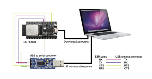
For the hardware connection of different models and more information click here click_here.
Using the terminal, navigate inside the folder containing the firmware you just extracted.
Eventually, replacing “PORTNAME” with the port to which you connected the “Download / Log output” connection, flash the firmware on the board with the following command.
esptool.py --chip auto --port PORTNAME --baud 115200 --before default_reset --after hard_reset write_flash -z download.config
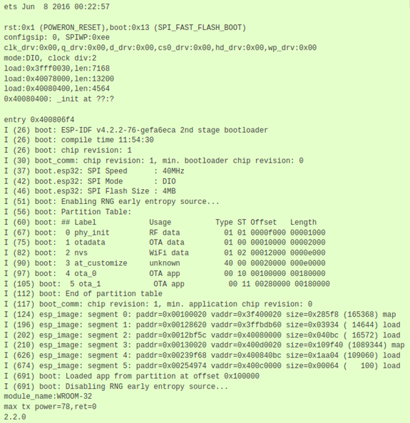
In the output log, if the process succeeded you should see a message similar to the following.
Now let’s make sure that the AT commands are working correctly.
To do this, you can use any program that can open a serial connection.
We in this tutorial explain how to use PuTTY, and how to set it up to communicate directly with the ESP-32.
Serial Connection: PuTTY
With the module still connected, look for the port name of the “AT Command/response” connection. (e.g. “/dev/ttyUSB0”)
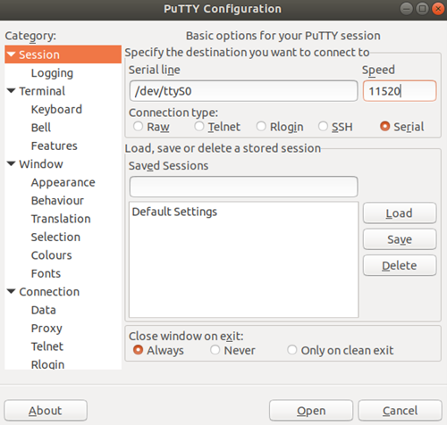
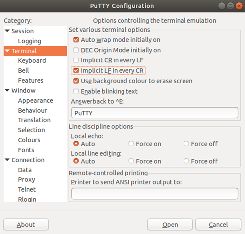
Select “Serial”. Then insert the name of your port “/dev/ttyUSB0” with the correct baud rate “115200”. In “Category”, select “Terminal” and tick on “Implicit LF in every CR”.
Finally, click on “Open” and start the communication.
Check ESP-AT command
We immediately verify that the commands are available.
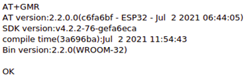
Let’s try to run the AT command “AT+GMR” followed by the special characters “\r” and “\n”, which are necessary for the board to receive the message.
NOTE: To produce them it is necessary to run the following keyboard shortcuts: “CTRL+M” and “CTRL+J” for “\ r” and “\ n” respectively.
The figure shows the response obtained from the execution of this instruction. If you get a similar message then you have successfully installed the firmware.
More information on how to properly install the firmware is at this link.
First example of BLE Server
A piece of cake!
With AT commands, just a few instructions are enough. We will now show you how to create a Bluetooth server that notifies a very simple “Hello World” message, to the first client that connects to it.
Assuming you have already connected the board, the first instruction to run is:
AT+BLEINIT=2Which has the effect of activating the Bluetooth Low Energy and setting mode “2” which corresponds to the server role.
If the command is executed correctly, the expected response is “OK”.
In order to actually make a connection you need to create a GATT service using the following command.
AT+BLEGATTSSRVCREOnce again the expected response is a simple “OK”.
Now we need to start this service. We use the following instruction, which returns “OK” to notify us of a positive outcome.
AT+BLEGATTSRVSTARTThen, we must start the “advertising” process that makes our service visible to all potential clients.
Go ahead and run the following instruction.
AT+BLEADVDATAEX="ESP-AT","A002","0102030405",0With this command, we have the possibility to specify both the name of our device that is visible to clients and the service we provide.
At this point the server is ready. We can now connect to our new server. To do this we can use a simple phone application, for example, “Serial Bluetooth Terminal”, or another ESP-32 in client mode.
To see how to do it click_here.
Let’s now see how to notify the first message.
On the server-side, run the following command to type the text you want to notify:
AT+BLEGATTNTFY=0,1,6,13Contrary to the previous commands, the output is not the “OK” message but you will see the “>” character. This will indicate that you can start typing text as in the following example.
> Hello_World\r\nSo, if the transmission succeeds you will see the final message “OK” on the screen.
Important! The server sends the notification only if it receives as input the number of bytes specified in the command and no more. In our case, they are 13. This number also includes special characters.
If you want more information on AT commands and how they work click_here, and for more examples of how to use them follow this link.
The Vivado Design
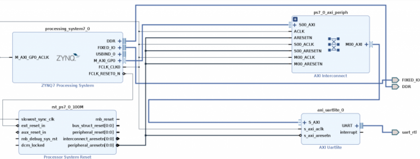
How can we use these features with Pynq?
Simple! Through a UART communication we can connect the two devices so we can send the AT commands to the ESP-32.
The design to create is super easy! Just add a “ZYNQ7 Processing System” block,then look for an “AXI Uartlite” block, run the usual “Run Automatication”, specify the correct constraints and that’s it.
You don’t know what we’re talking about and want more details? click_here to see our article on how to create a UART communication on Pynq.
Important! If the two devices do not communicate, change the baud rate of the ESP-32 module to 9600.
Open a terminal and connect to the “AT Command/response” connection port. And run the following commands:
AT+UART_DEF?It will show you the UART communication settings saved in flash
+UART_DEF:< baudrate >,< databits >,< stopbits >,< parity >,< flow control >

OK
If the baud rate is not 9600, enter the following command.
AT+UART_DEF=9600,8,1,0,3This changes the settings and It will save them in flash.
Pynq-z2 as BLE Serve
The last step to correctly connect the Pynq with Bluetooth Low Energy is to extend the UartAXI class that you can find here. More precisely in the “UART” folder inside the uart_test.ipynb file.
These modifications allow sending the necessary commands to the ESP-32 module. And therefore to correctly notify messages to the possible connected clients.
Below we will show an example of how to create a wrapper method to add to the UartAXI class:
def  bleinit_server(self):
    mode = 2     #server
    cmd = "AT+BLEINIT=”+ str(mode) + ”\r\n"
    self.write(buf=cmd)
    res = self.read(count=100, timeout=5) # the return is “\r\nOK\r\n”
    print(res)
    err_msg = False
    if res.find("ERROR") != -1:
        err_msg = True
    return err_msg
The reader can extend this simple method with any other AT command, obviously, we note that according to the command the inputs and outputs may differ.
Finally, to create the main function for our Bluetooth server on Pynq, we just need to call all the wrappers to the AT commands in order to reproduce the BLE server example we discussed earlier 🙂
Thanks a lot for your attention.